![]()
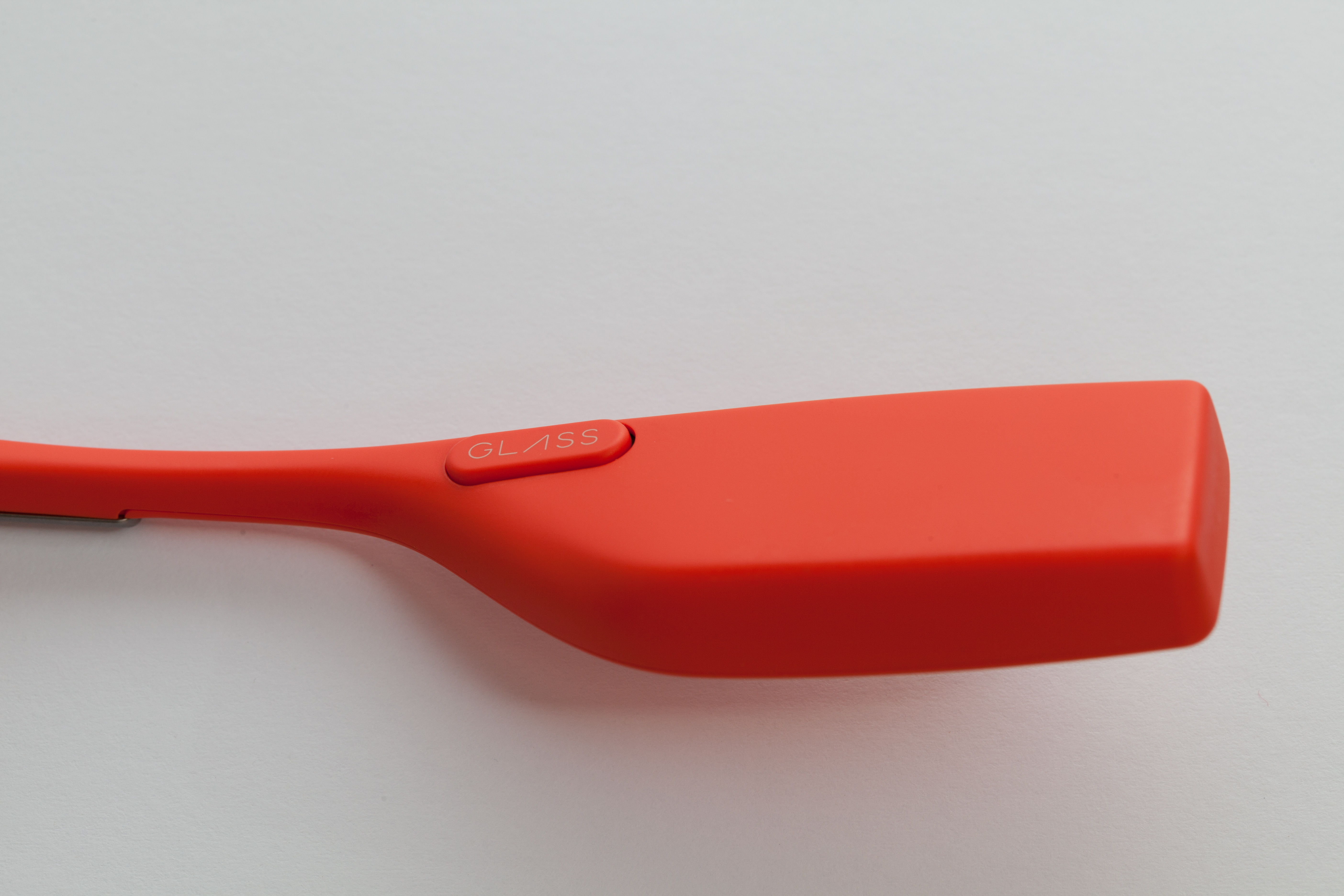
Hardware Teardown
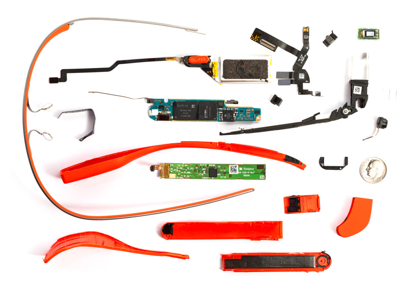
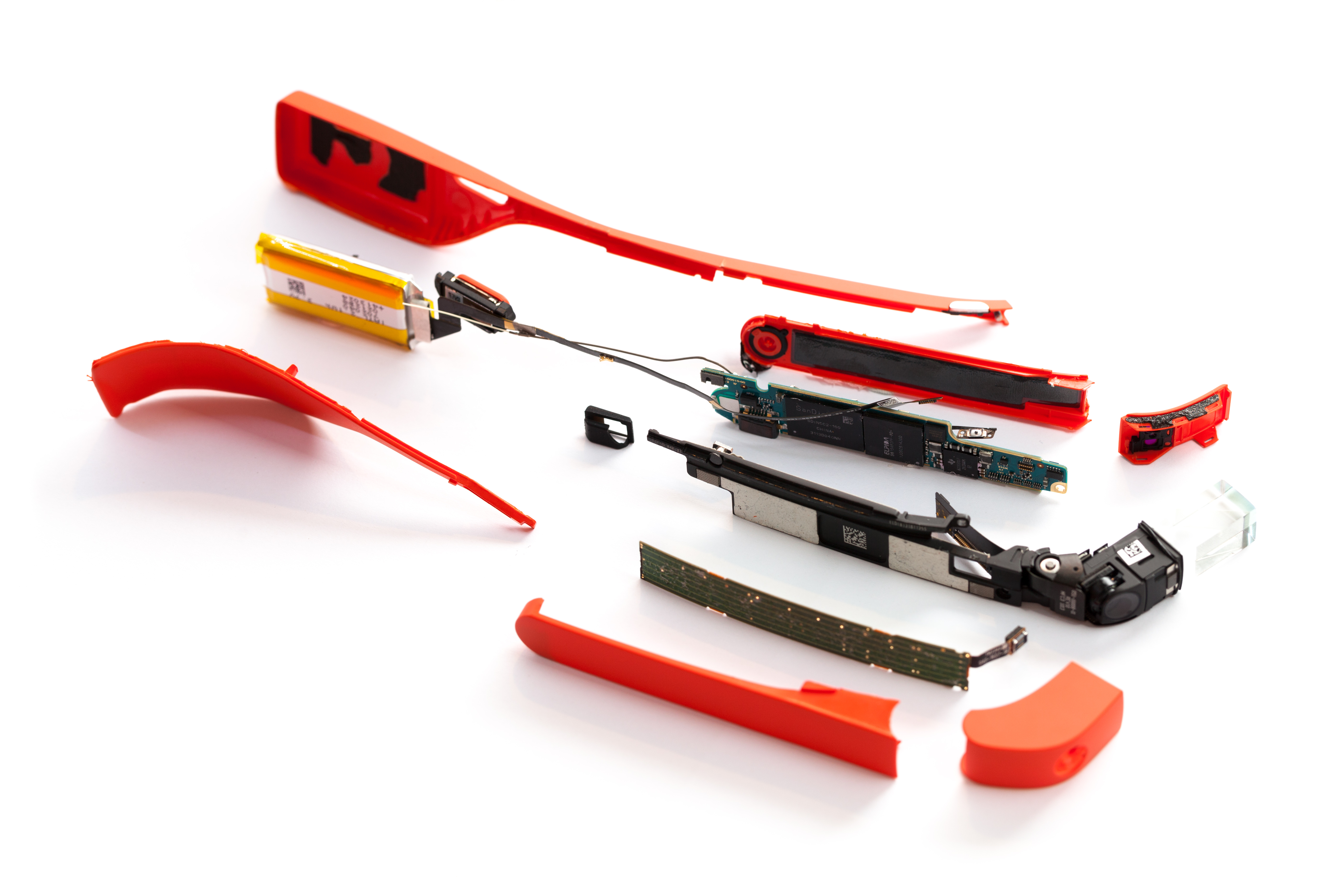
We eagerly brought Glass back to the lab to begin the dissection. Speculation reigned: what if the entire body of Glass is potted with epoxy requiring strong solvents to access? Which part is the battery in? How hackable is this thing? Where are the sensors? Any extra hardware features yet to be unlocked by future software updates? But first, where to even begin opening it?
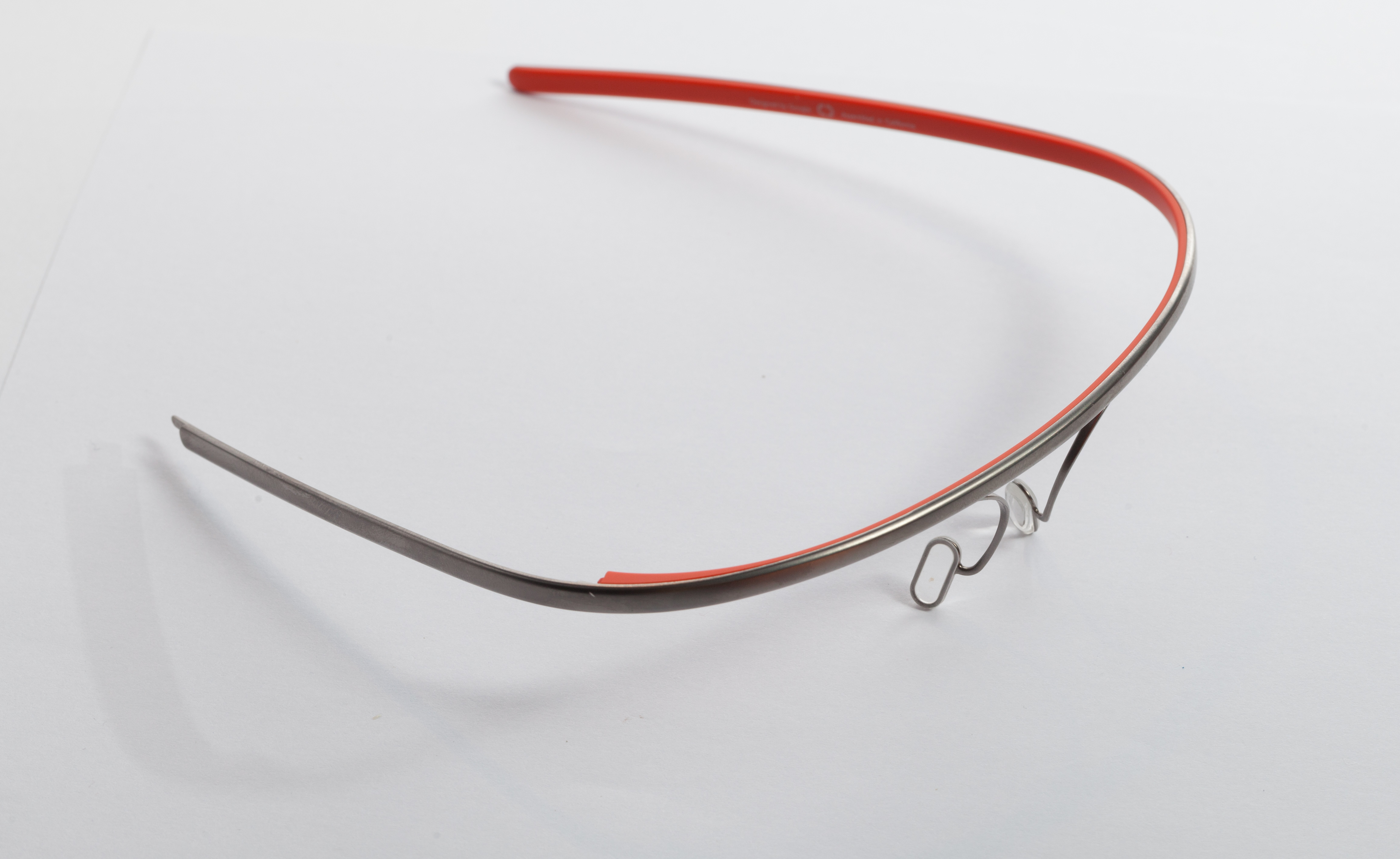
With no idea of what lay ahead, we started by removing the titanium frame from the pod that holds all the good stuff.
Please Note: Much of the disassembly ahead was specialized, and required a certain precision in dexterity to pull off. That said, if you're careful and familiar with disassembling consumer products, Glass did not seem to present any major lurking hazards of inadvertent disassembly damage to components. As a testament to this, we were able to reassemble Glass after this teardown and it still operated perfectly, albeit with cosmetic damage.
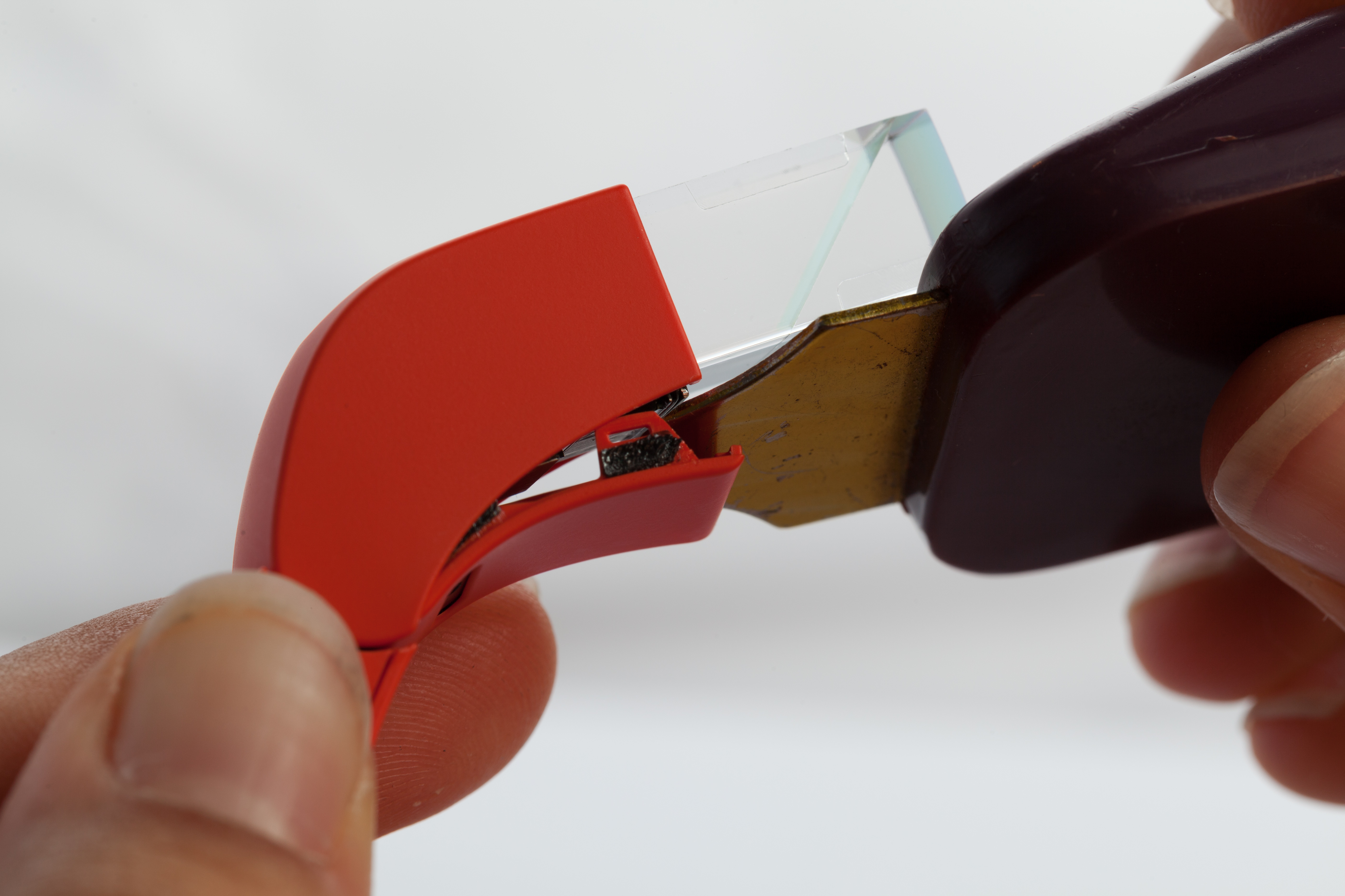
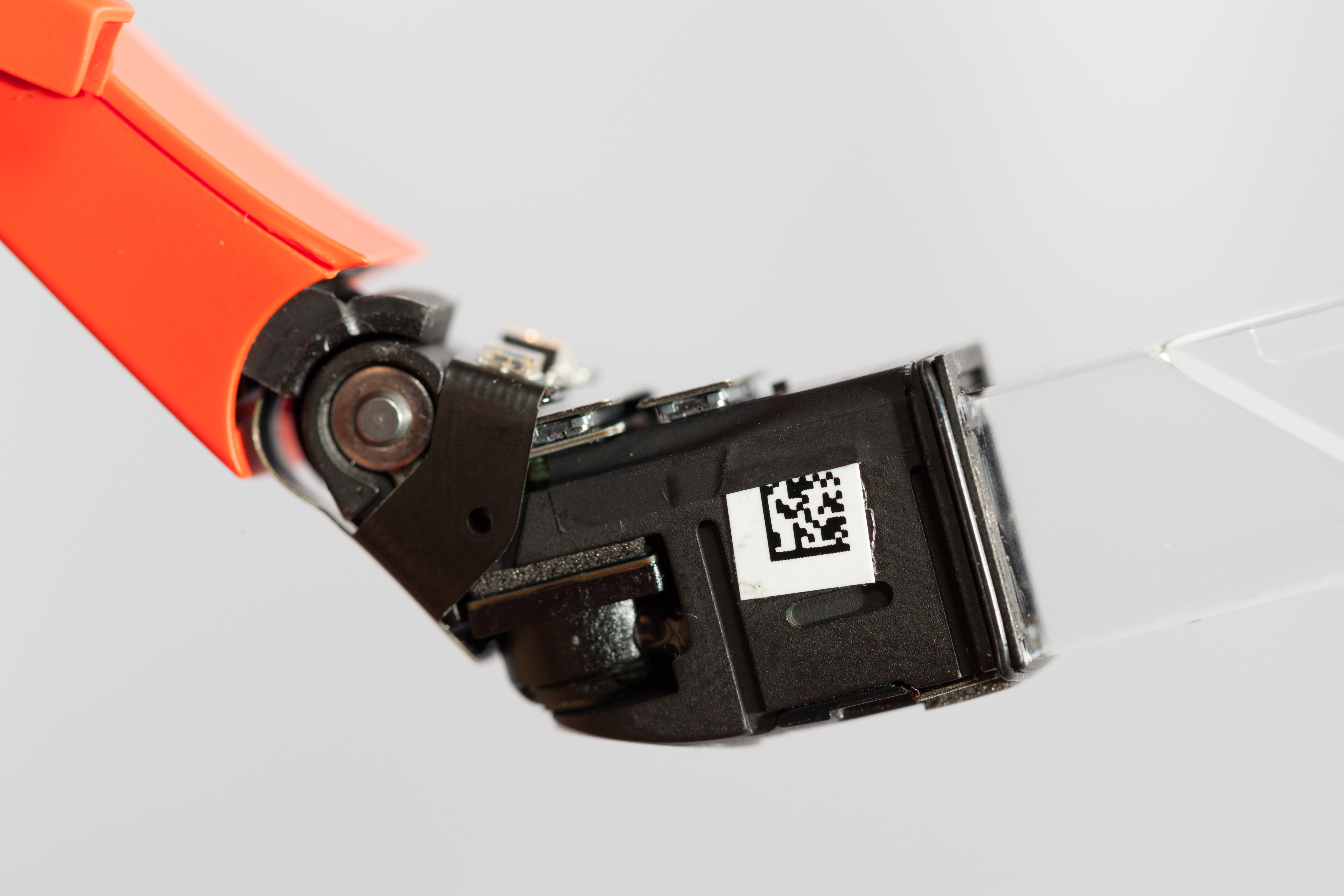
Removing the Pod
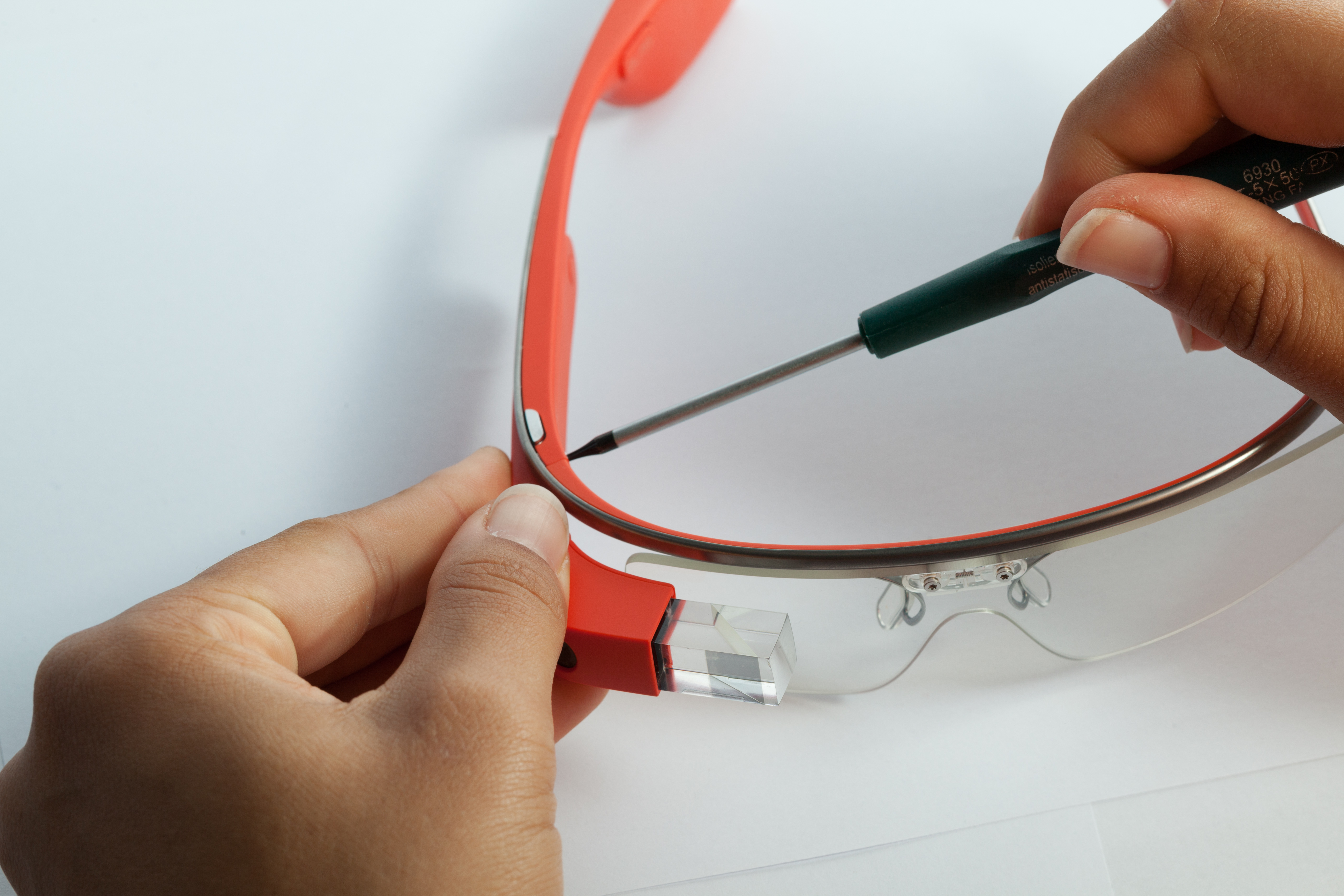
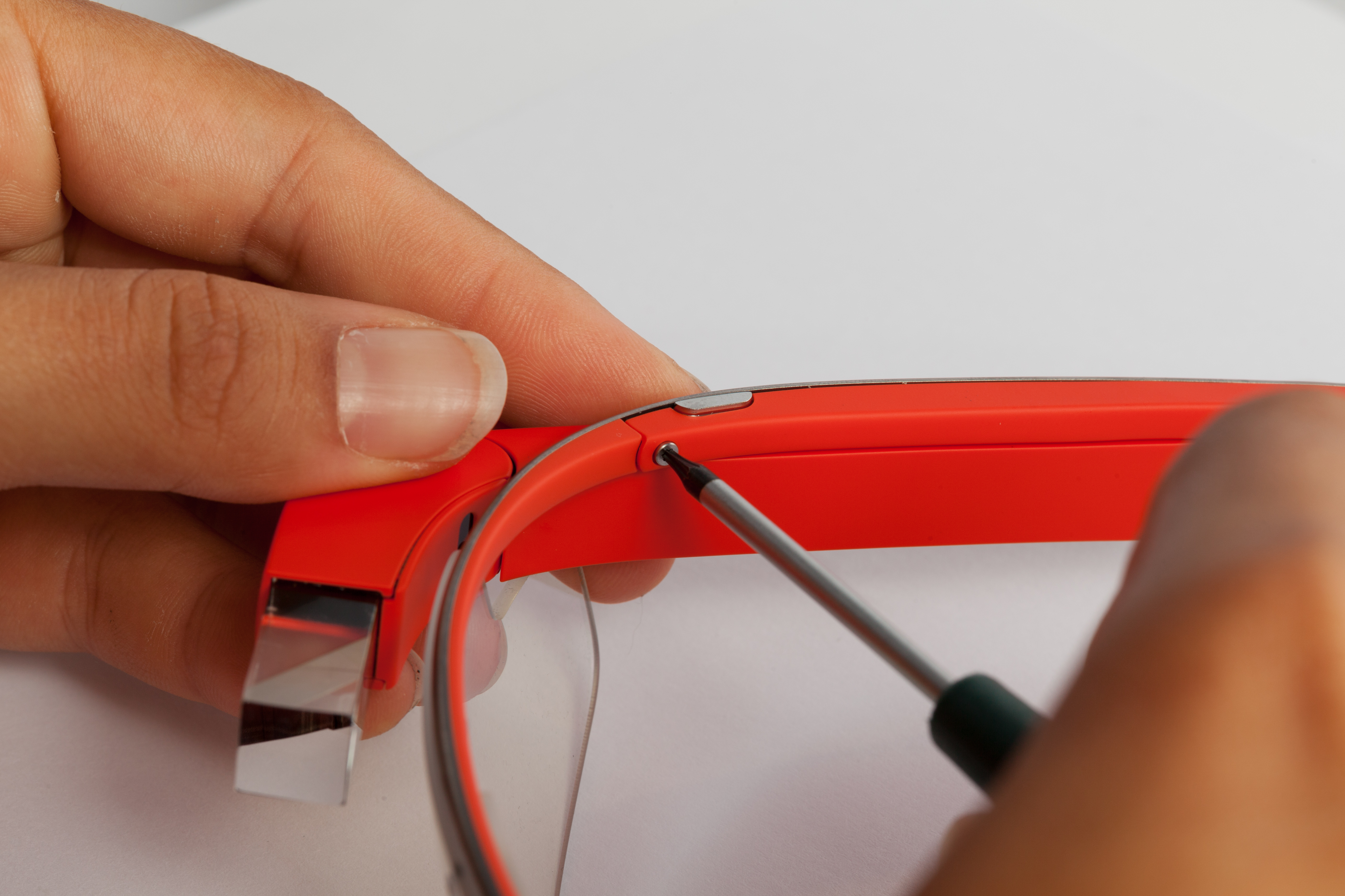
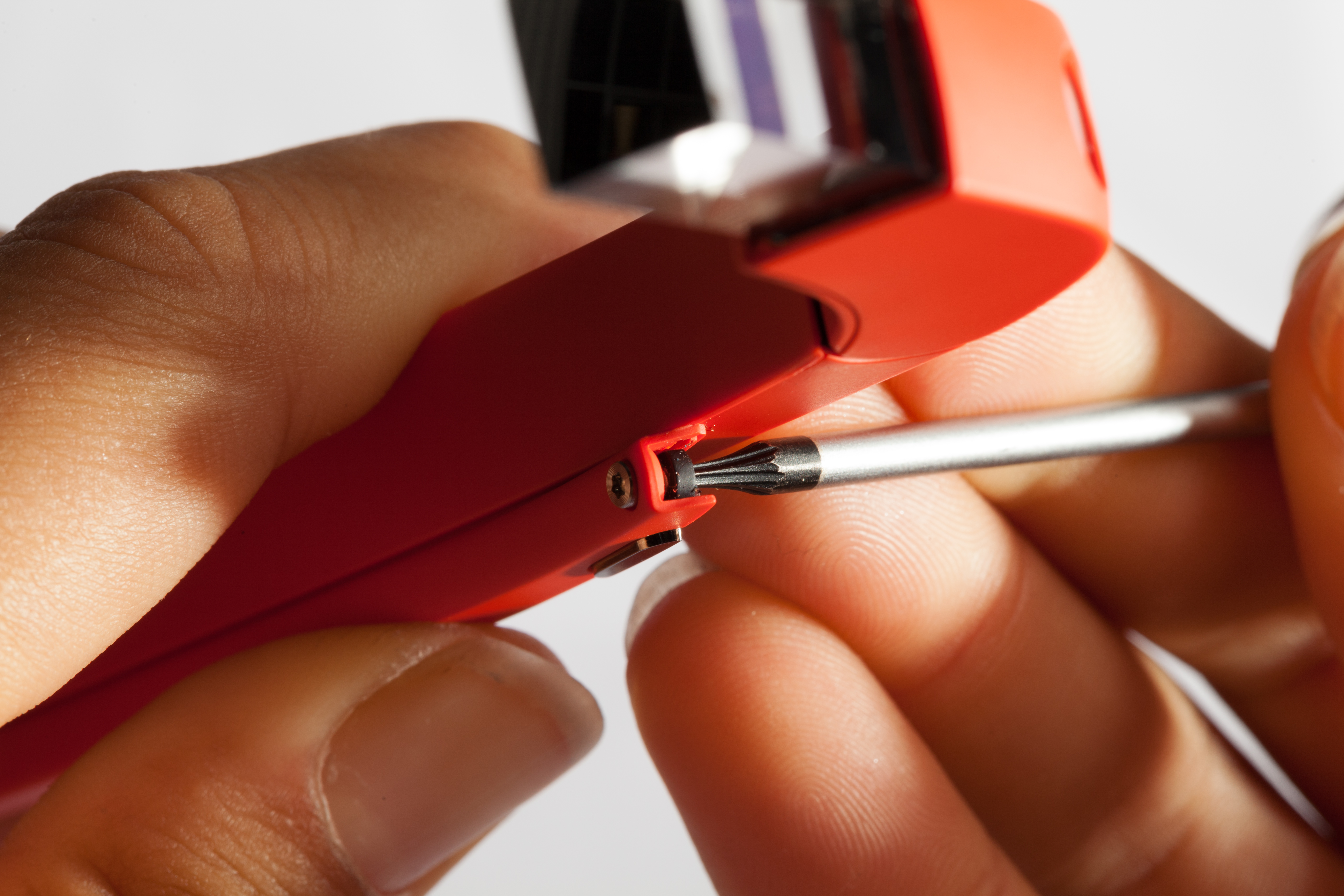
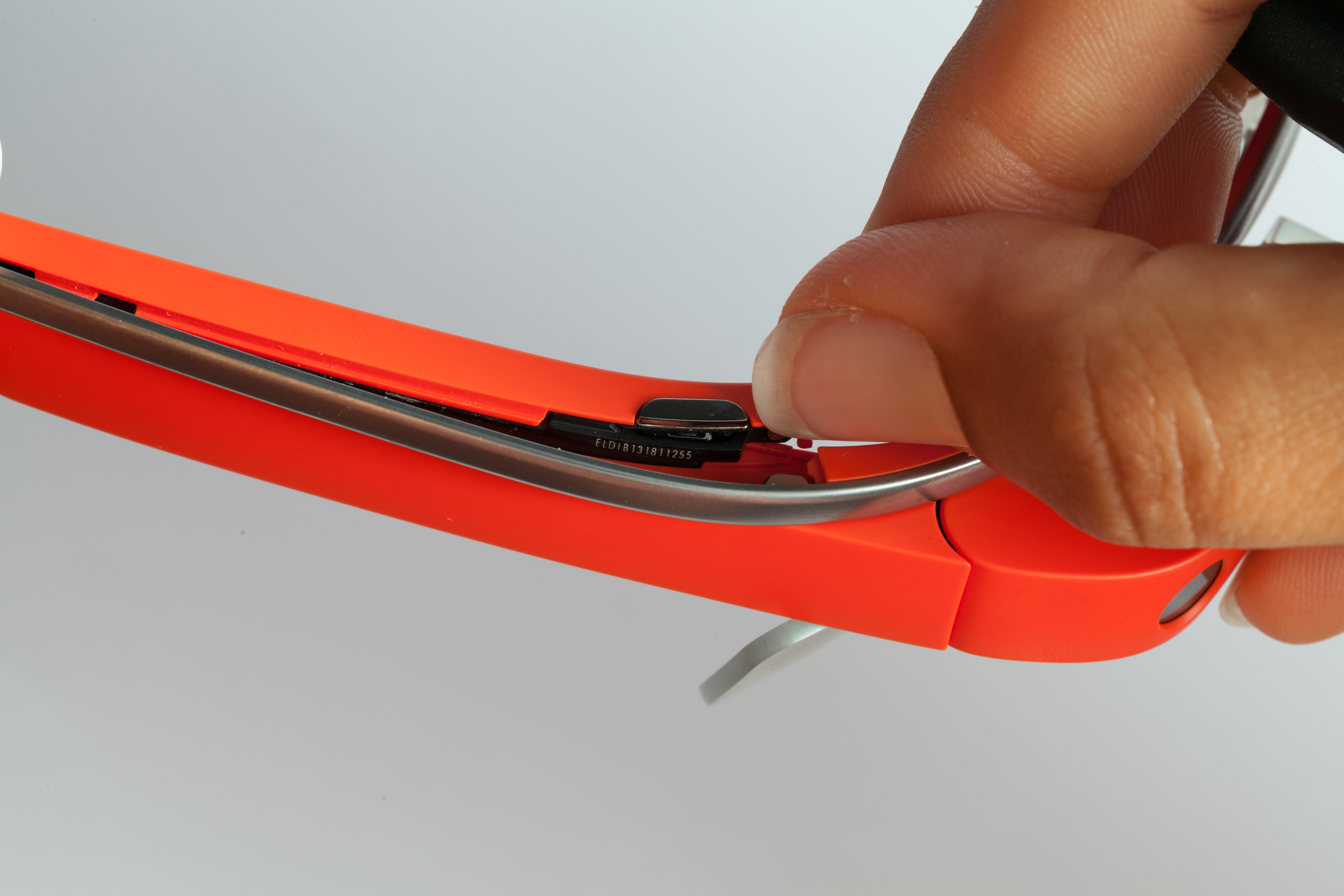
The initial entry point into the Glass enclosure is a single Torx T5 screw. This screw removes the "pod" from the main titanium frame, and is likely intended to be user-serviceable. We detached the frame and set it aside. Removing this screw also enabled us to read the Glass unit's serial number, tucked against a black surface behind the frame.
Officially, Glass isn't currently compatible with prescription glasses, although plans are in the work to support them. However, as a random experiment, we tried simply attaching the Glass "pod" to a pair of prescription frames.
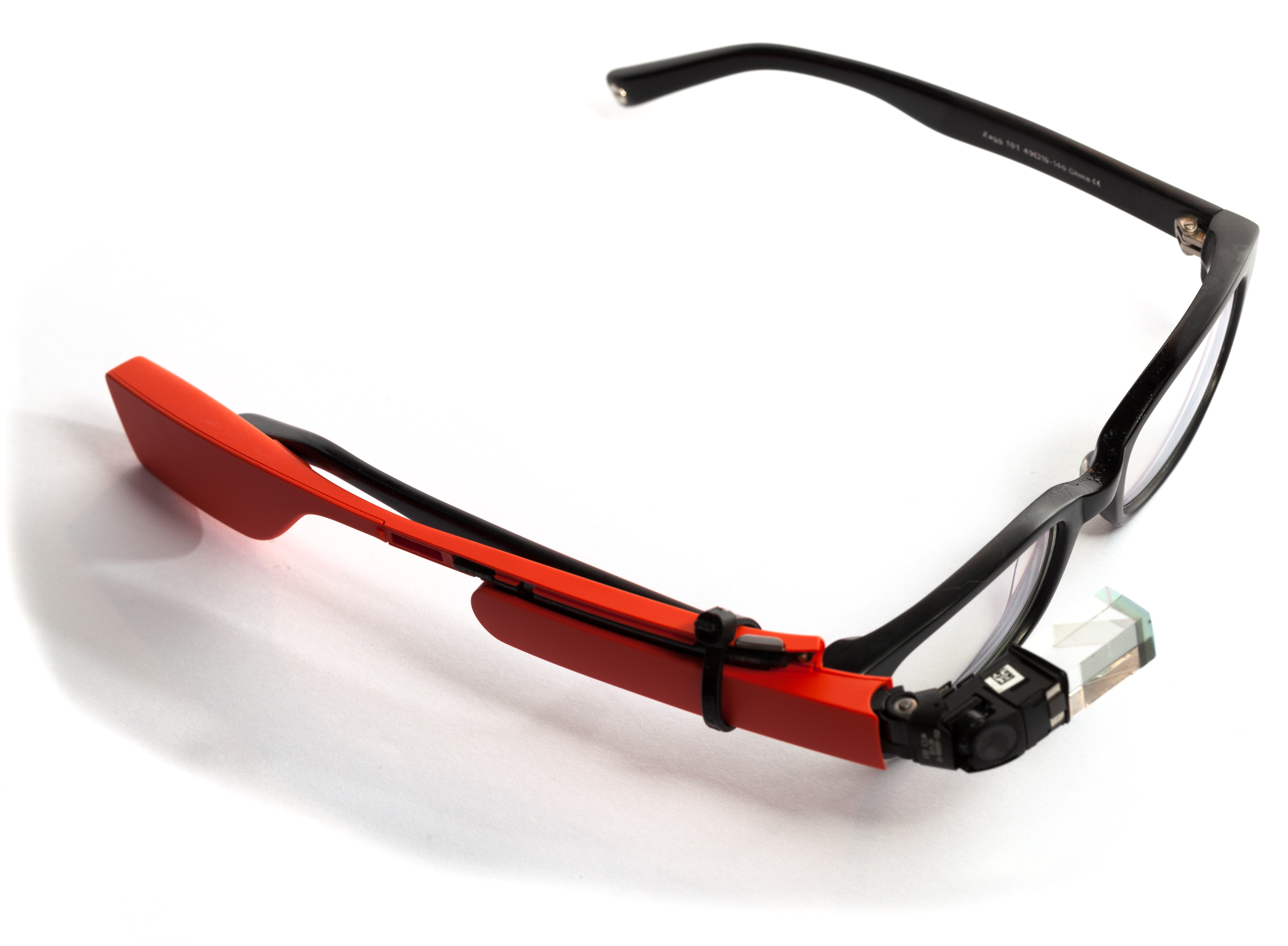
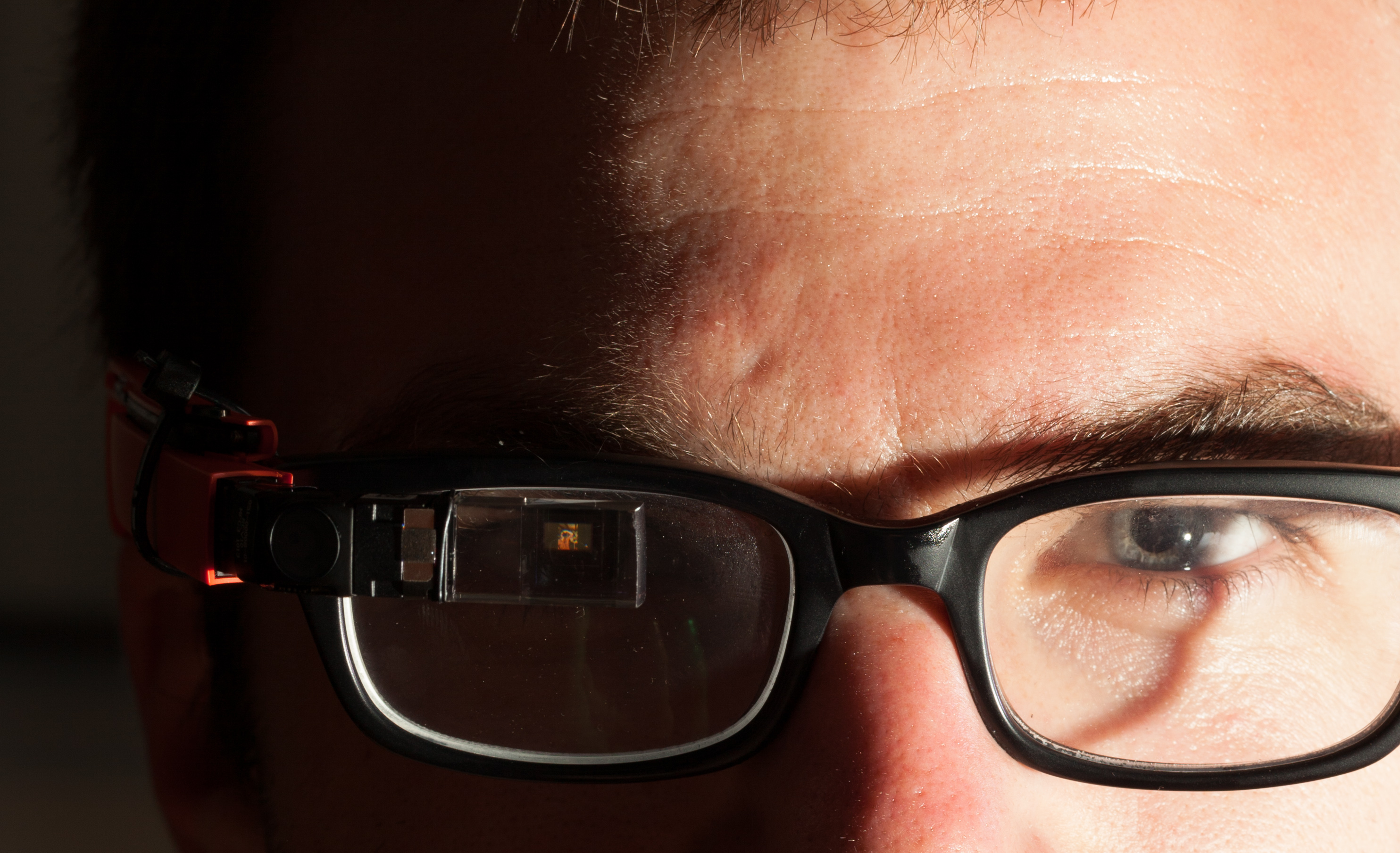
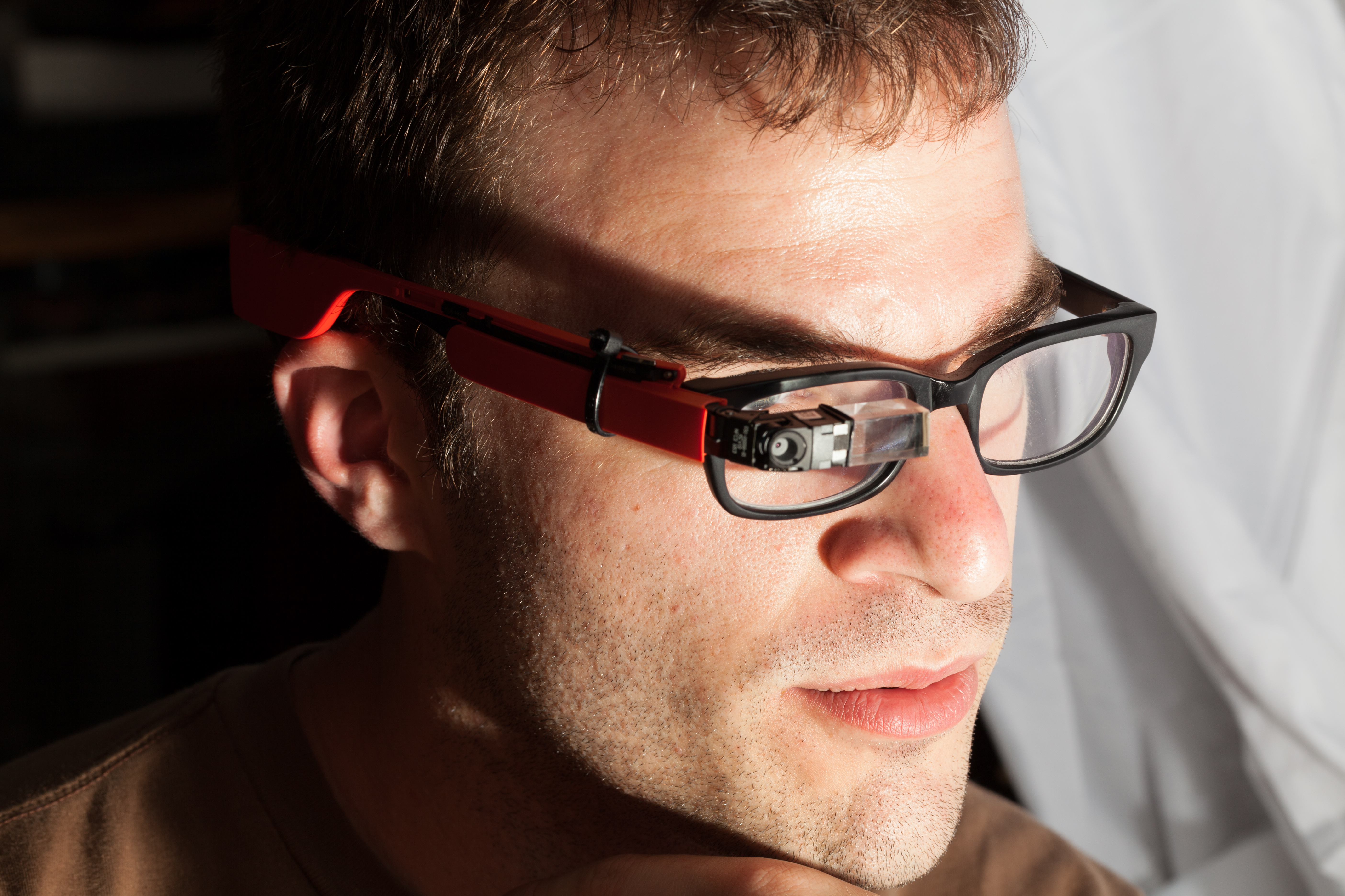
Although functional, the experience was subpar, because the head proximity sensor was very unreliable when next to a lens.
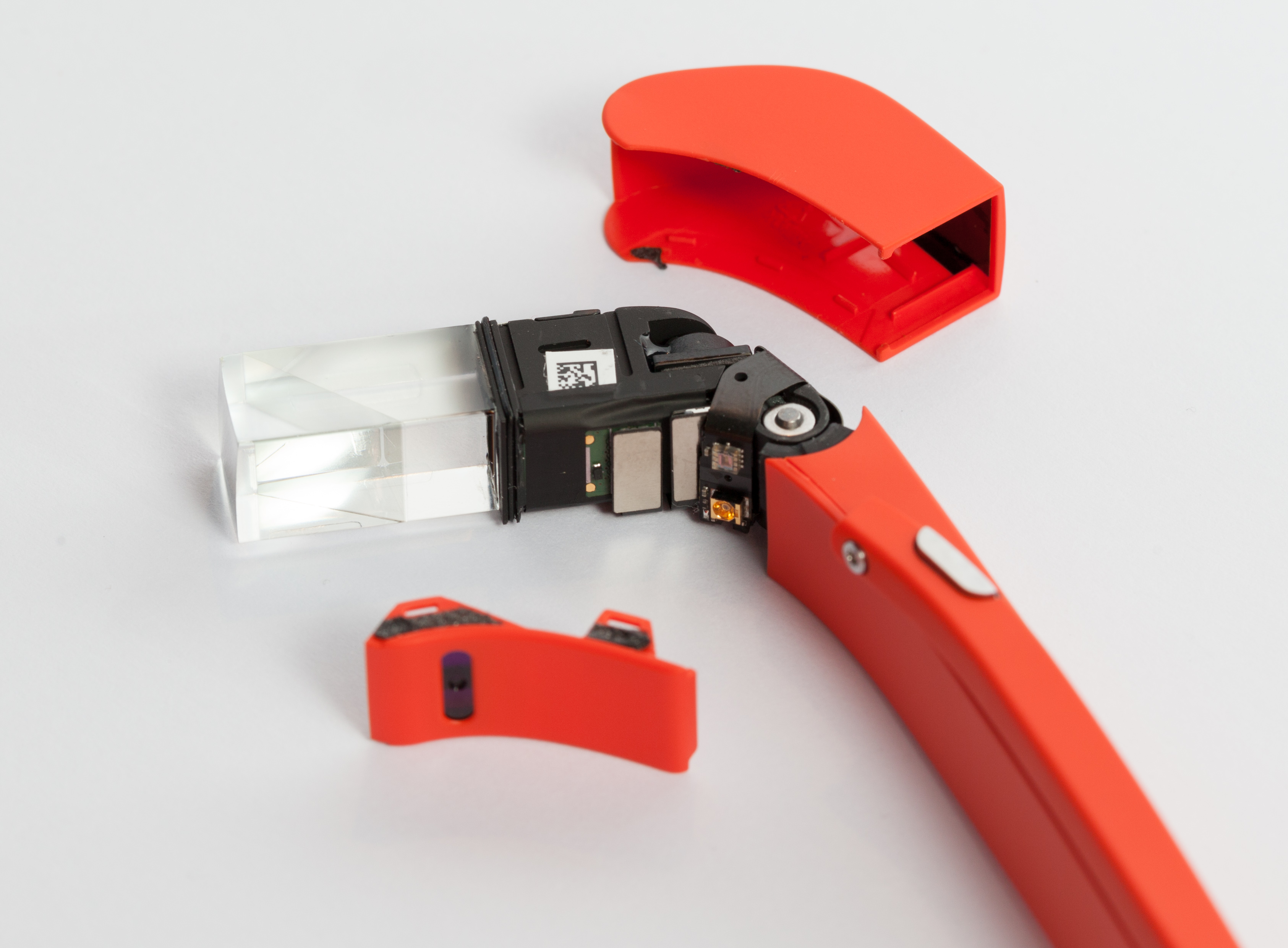
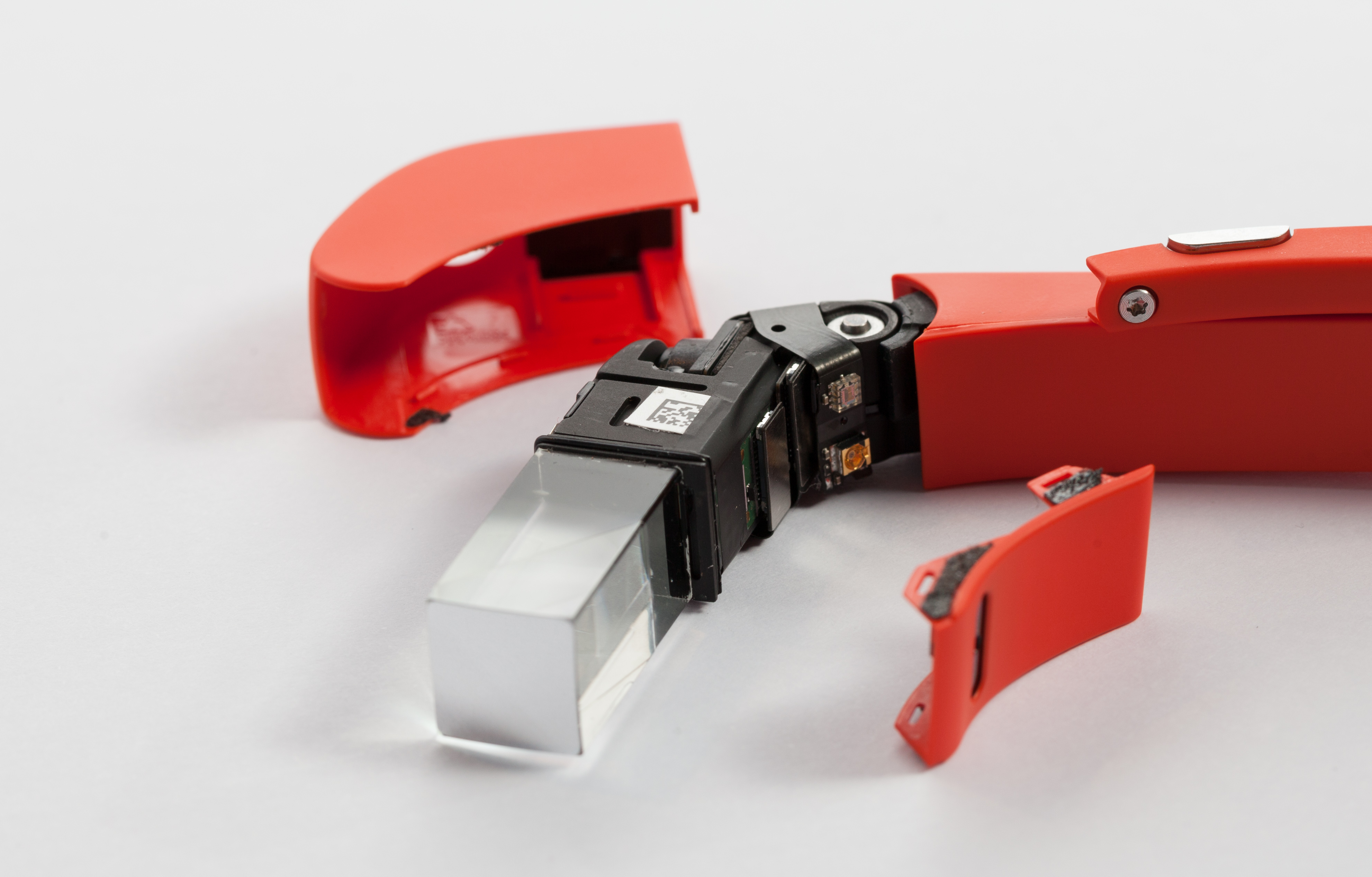
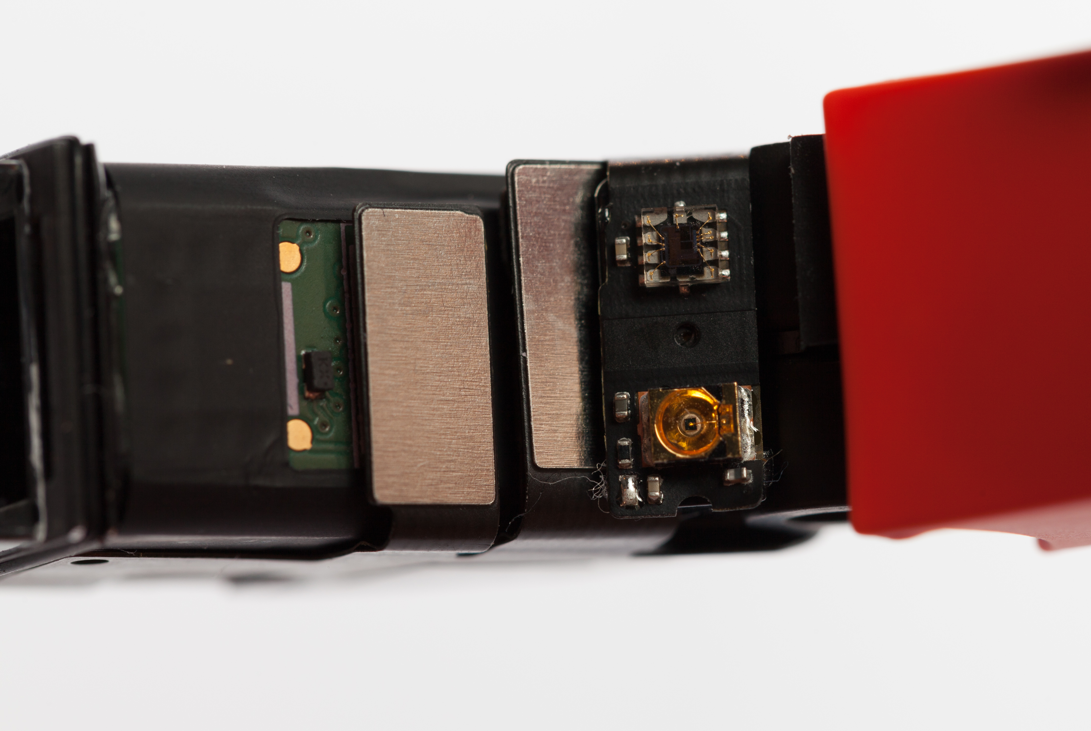
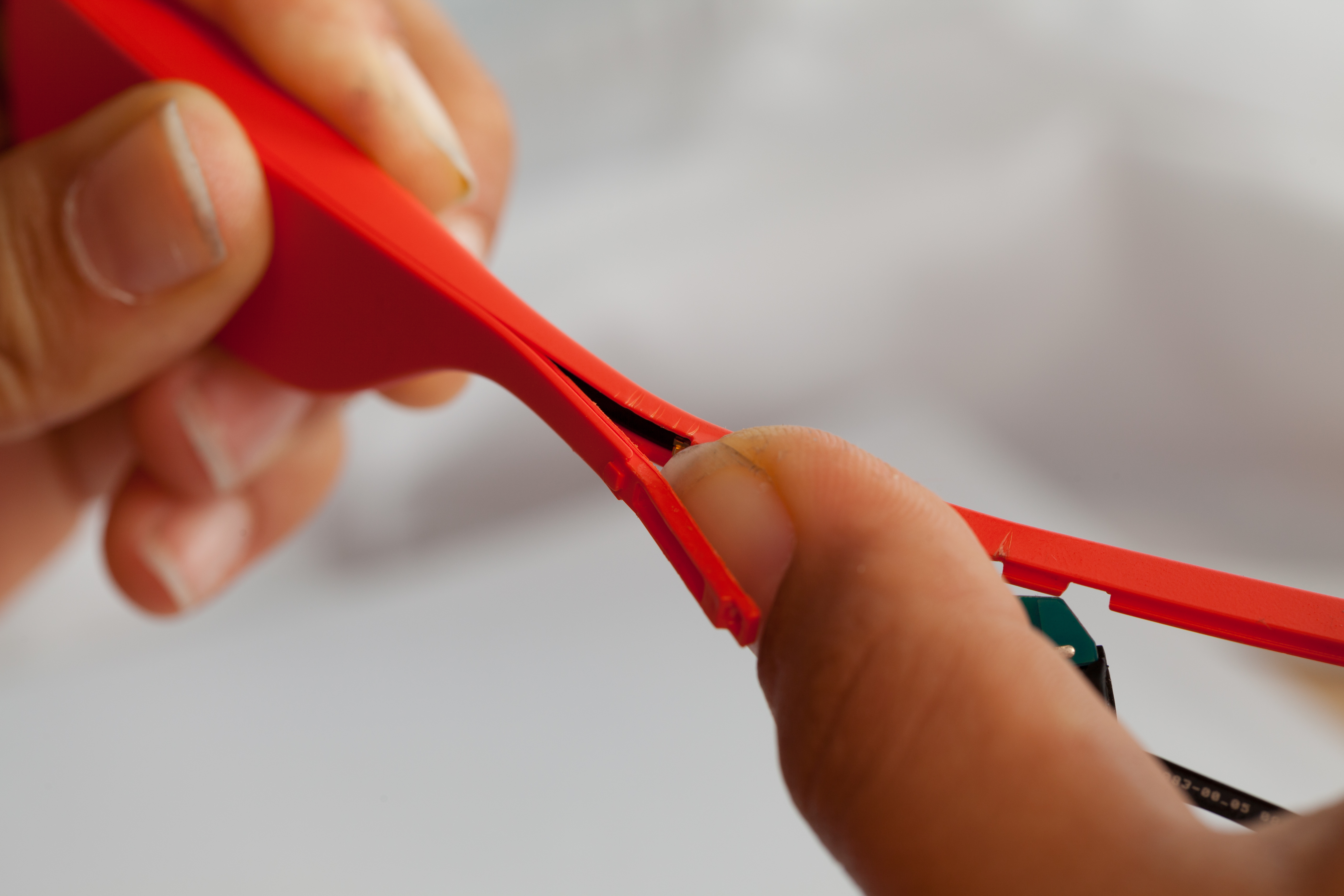
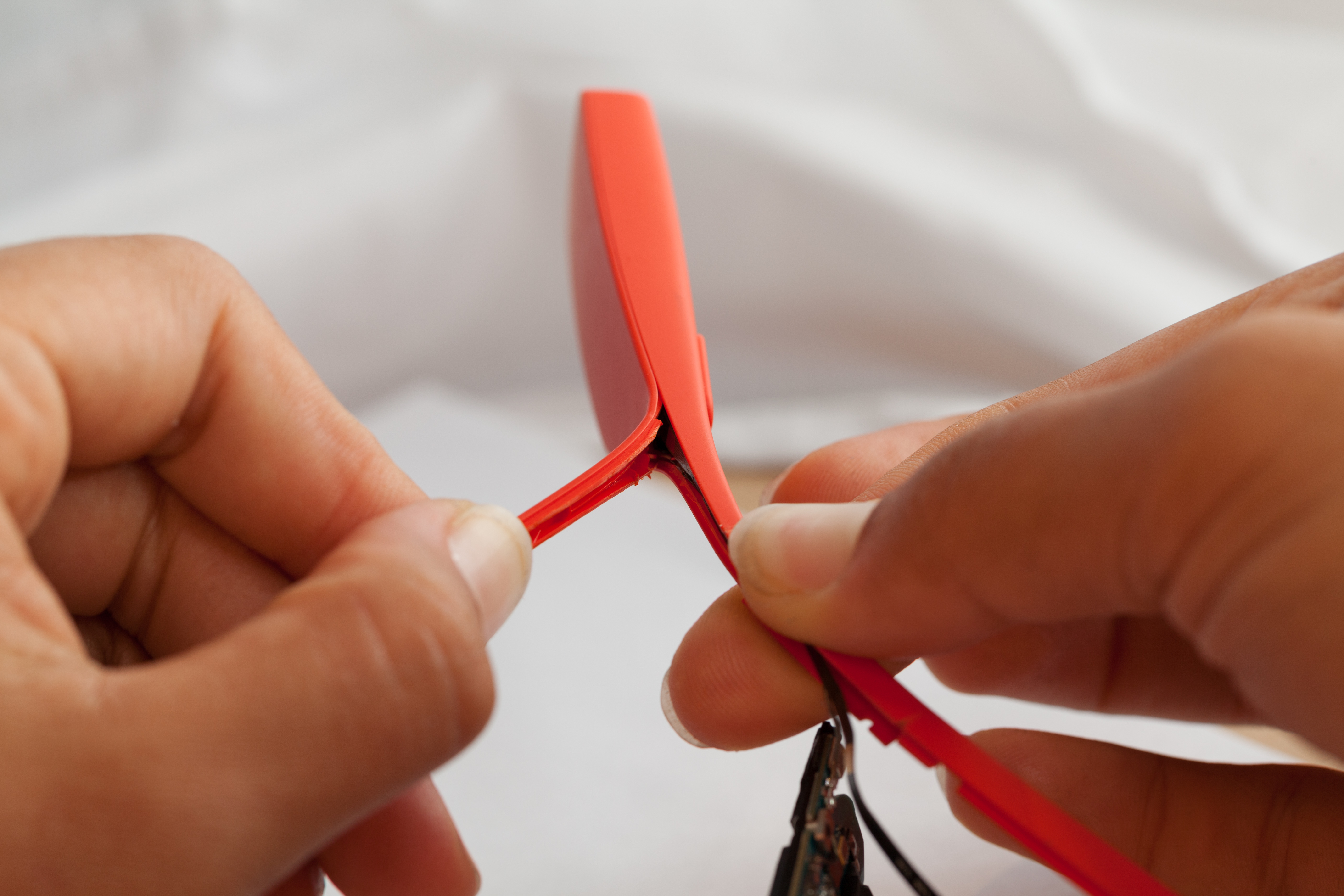
Opening The Case
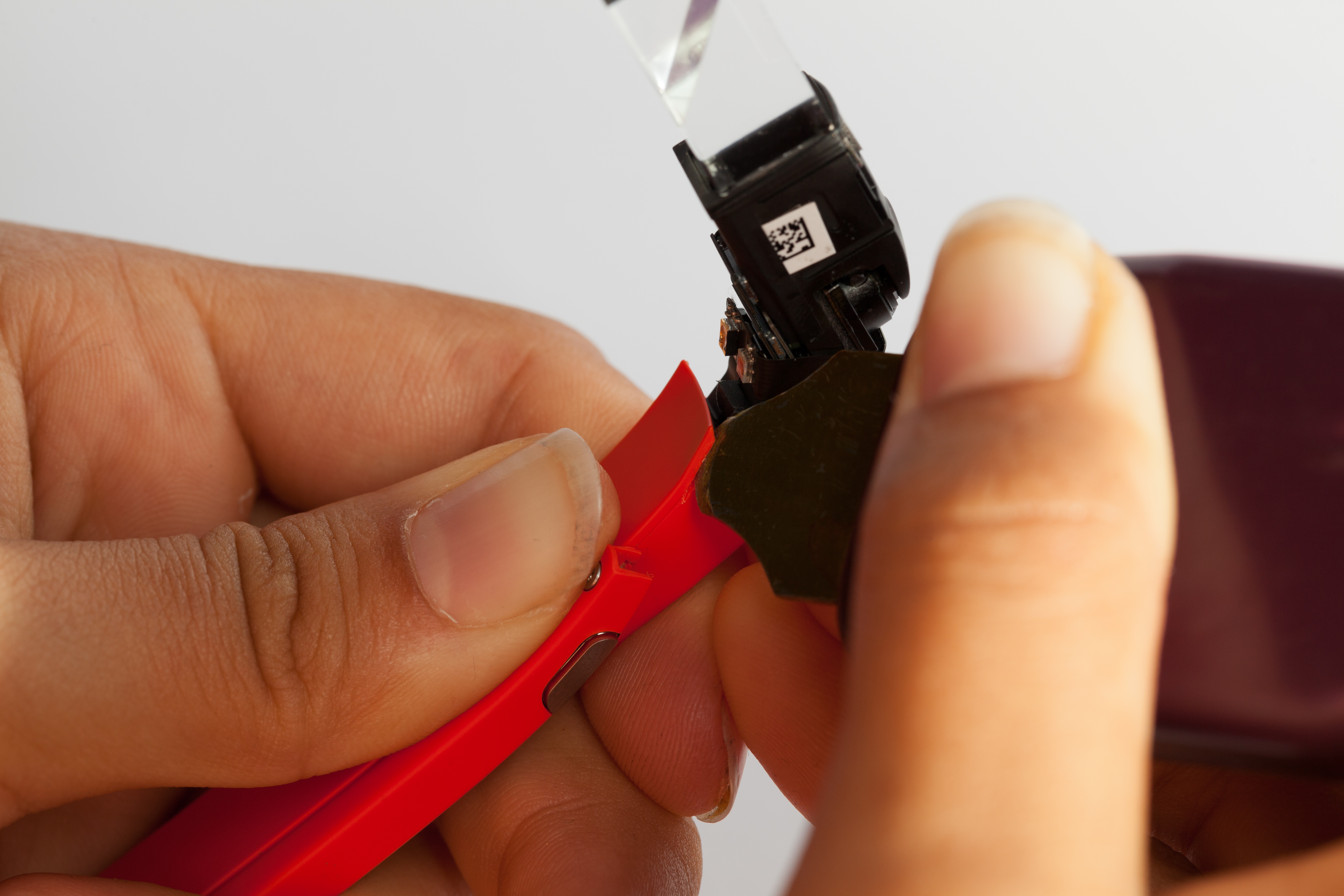
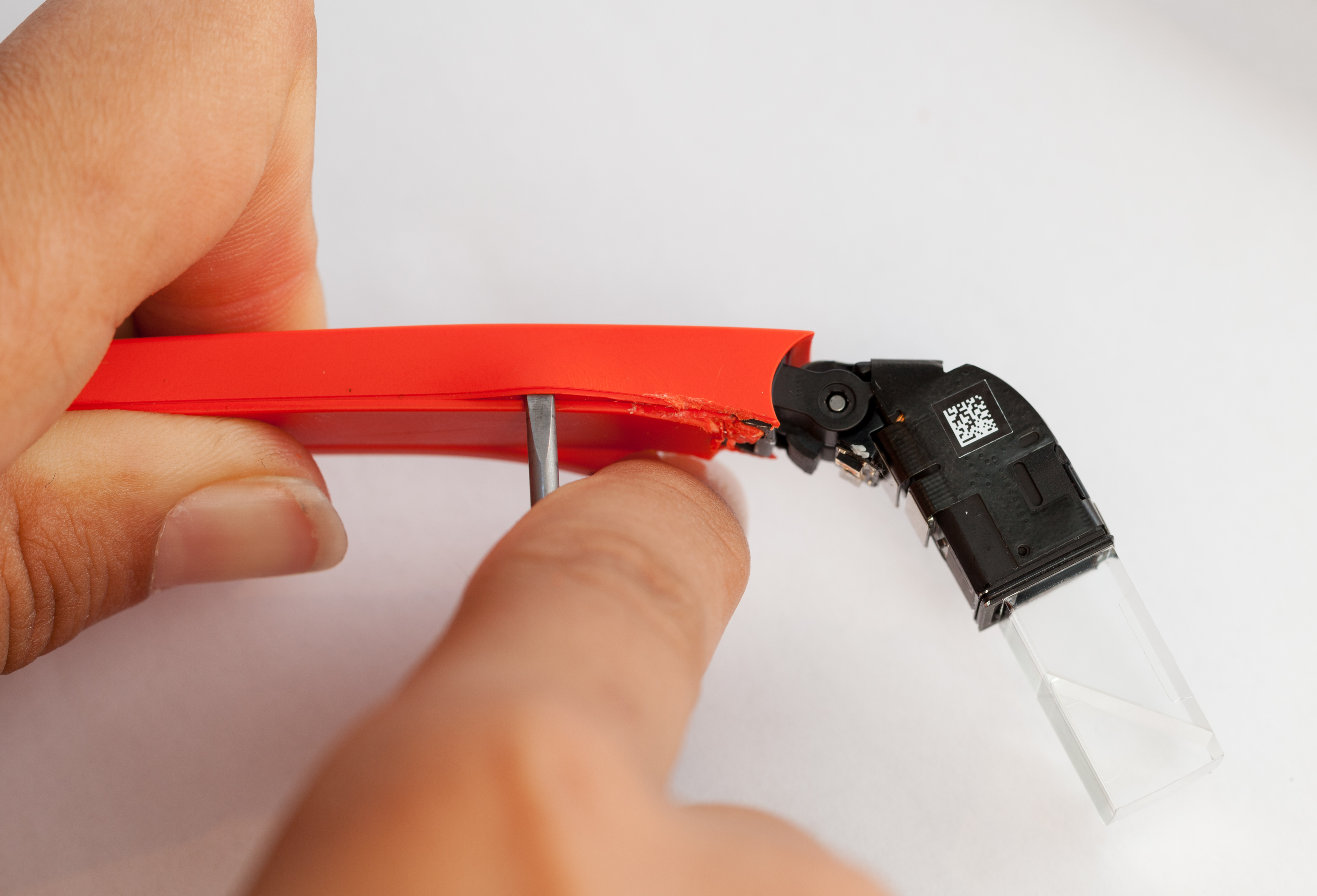
First we pried off the plastic casings around the display, located just next to the main prism.
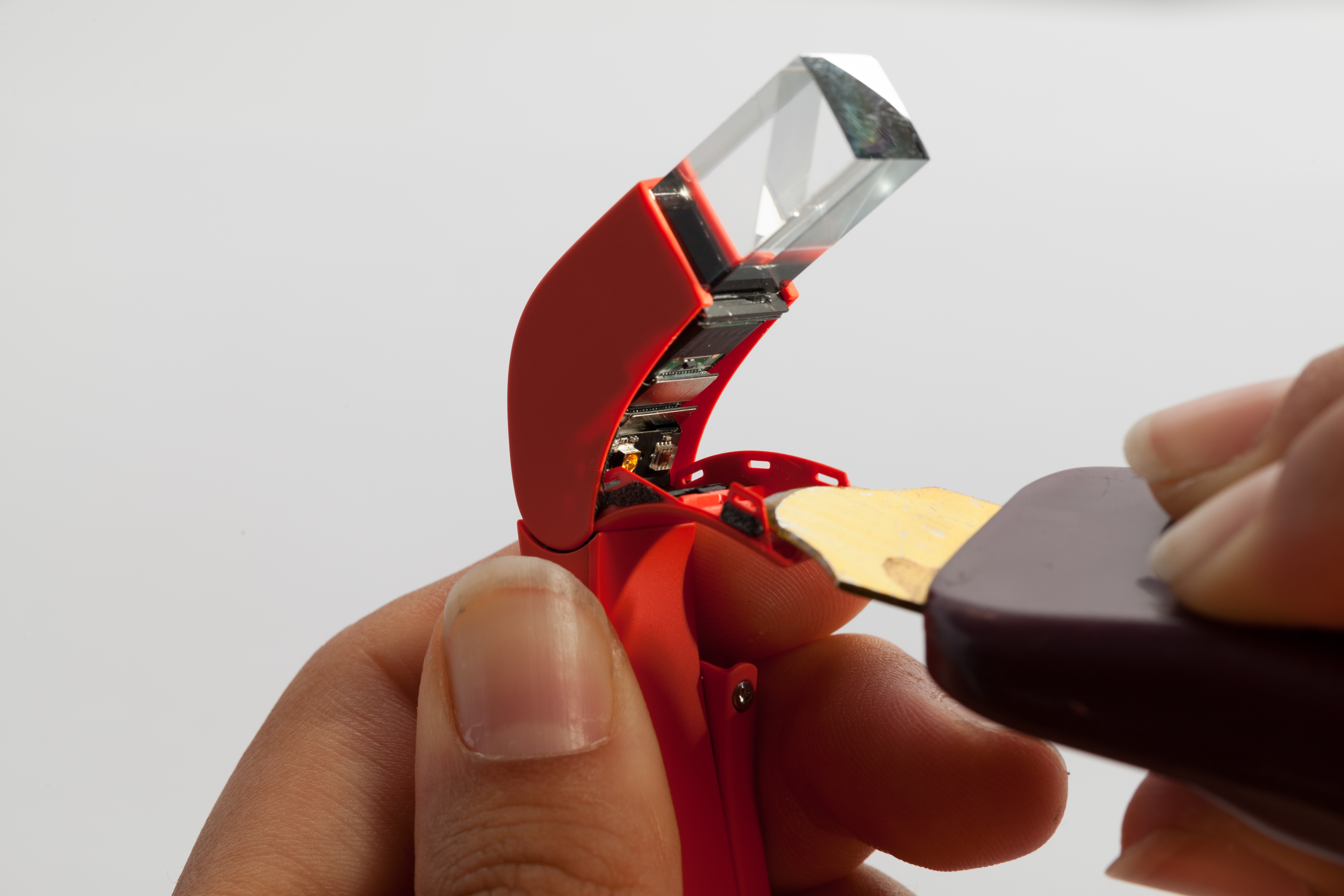
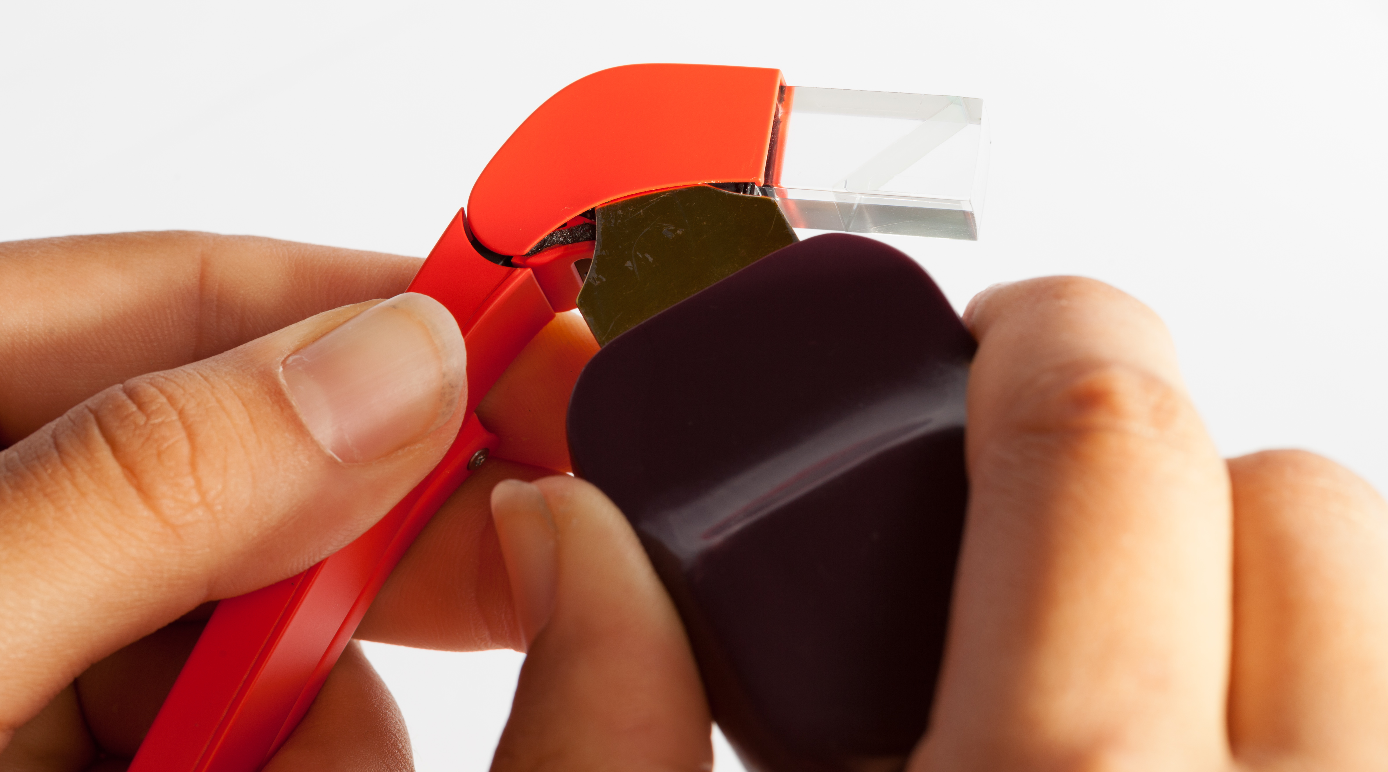
This exposed the proximity sensor and what appears to be an ambient light sensor.
At this point we saw no obvious means for removing more plastic. We carefully prodded with spudgers and screwdrivers, but ultimately found an internal screw that was difficult to remove non-destructively. We applied force and leverage, cut a bit around the internal screw, and peeled back the outer shell. We then removed the now-exposed internal screw.
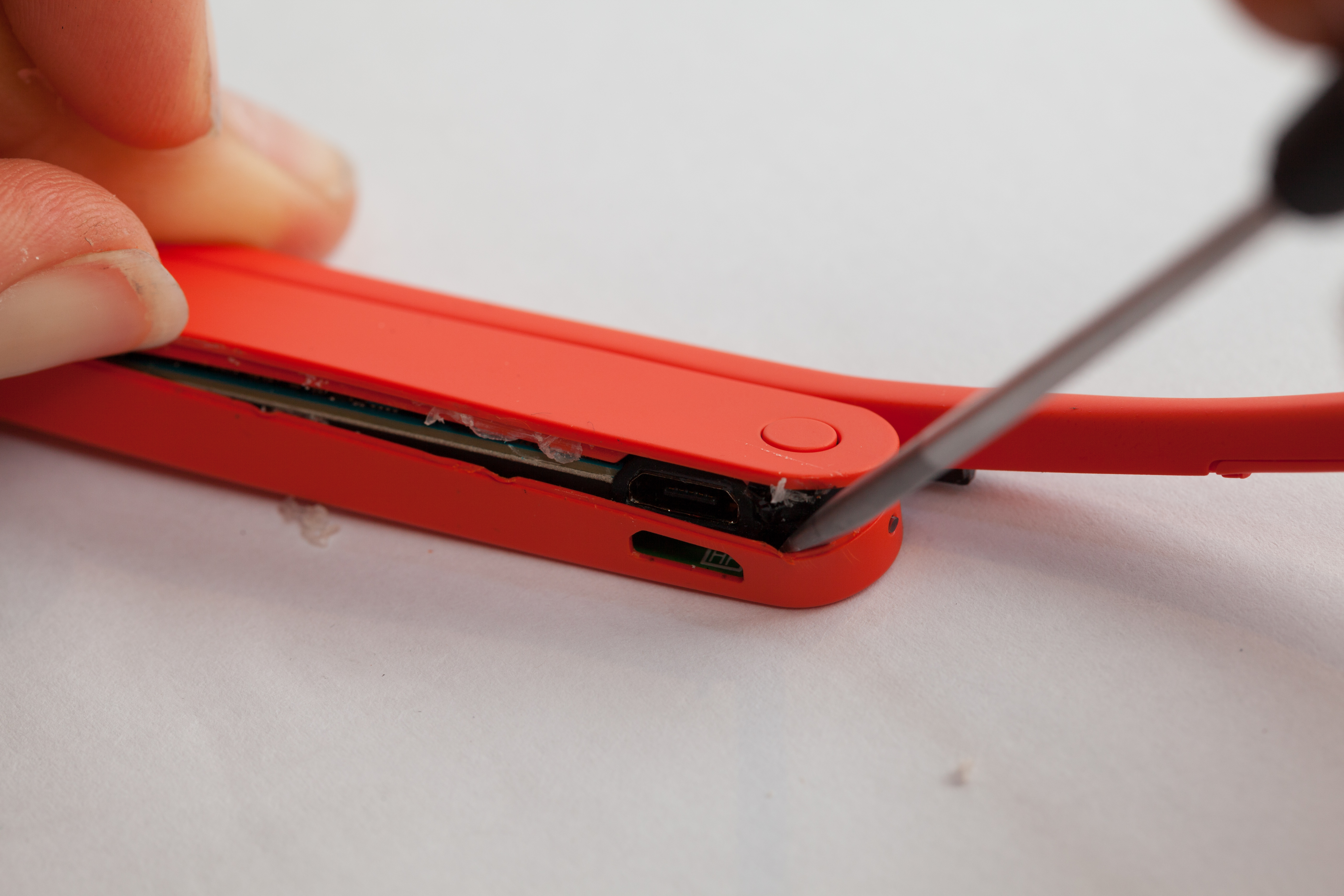
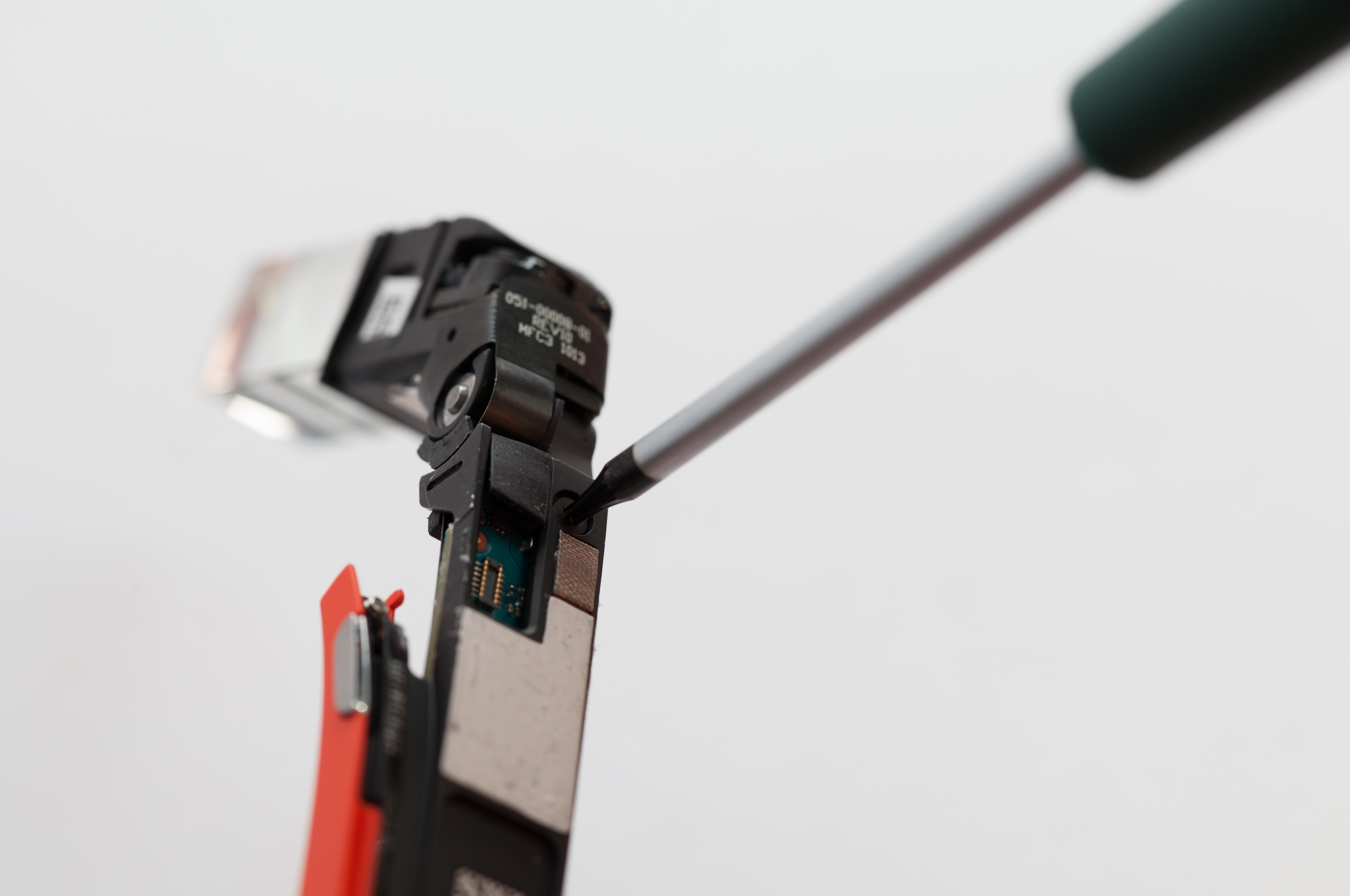
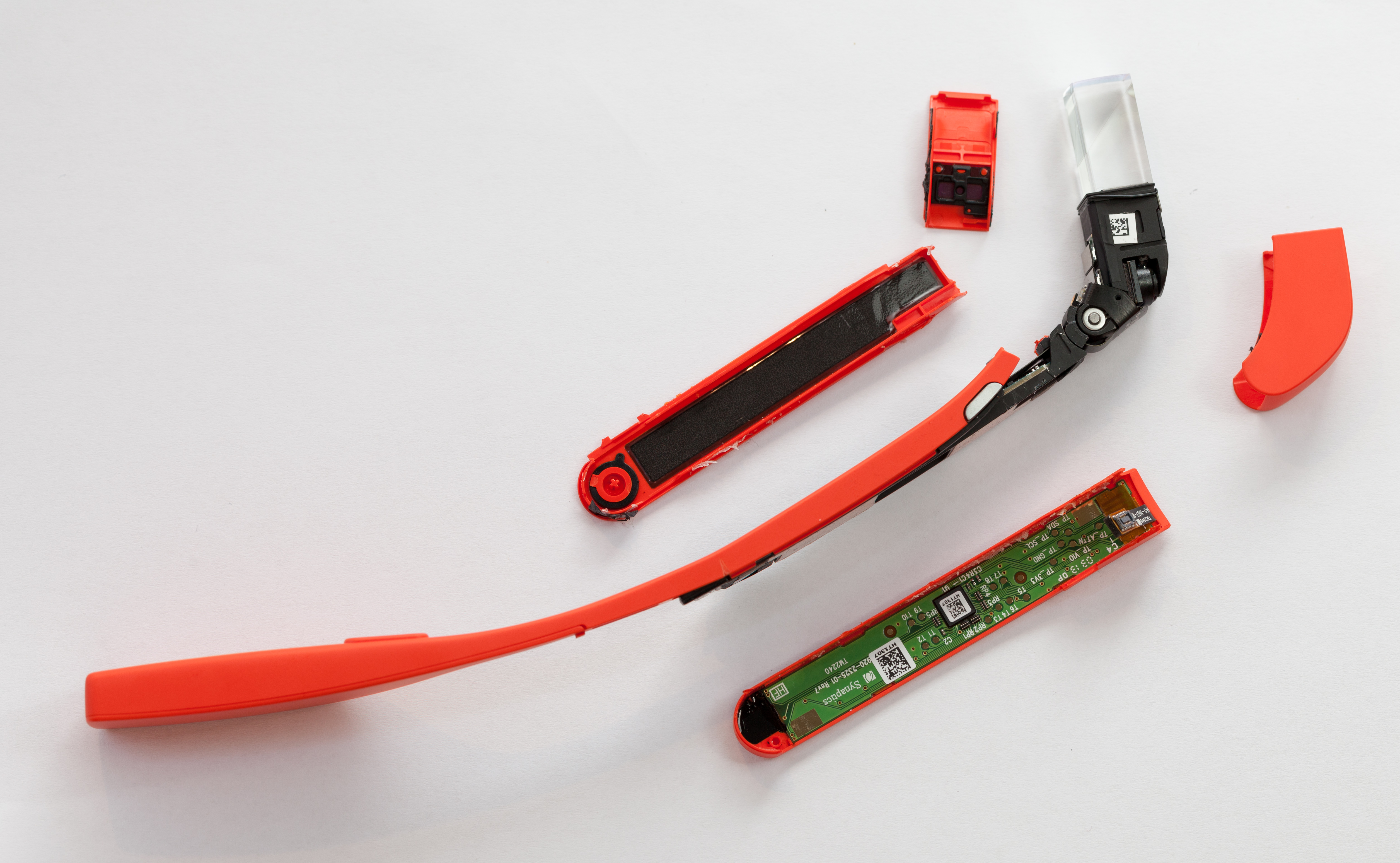
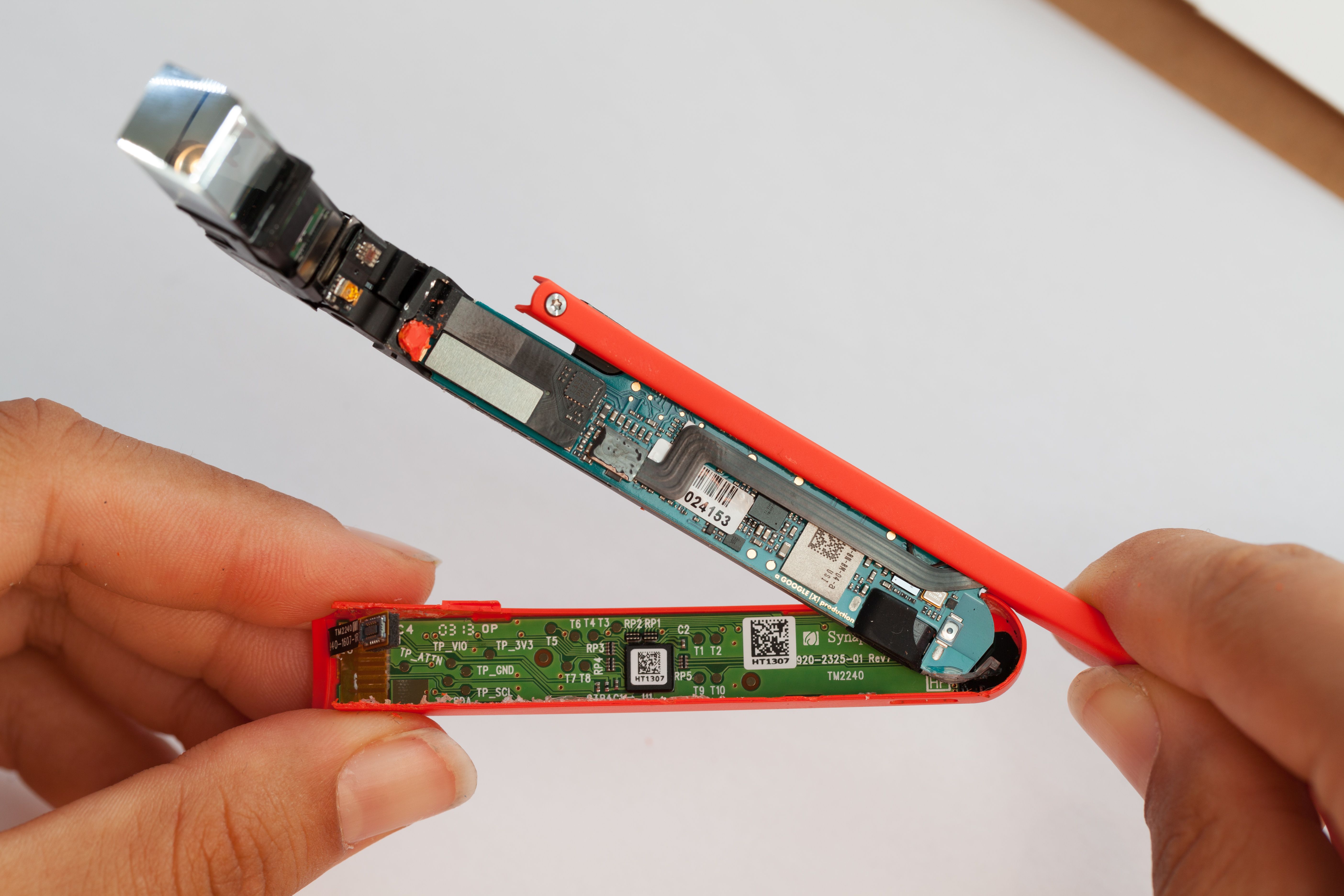
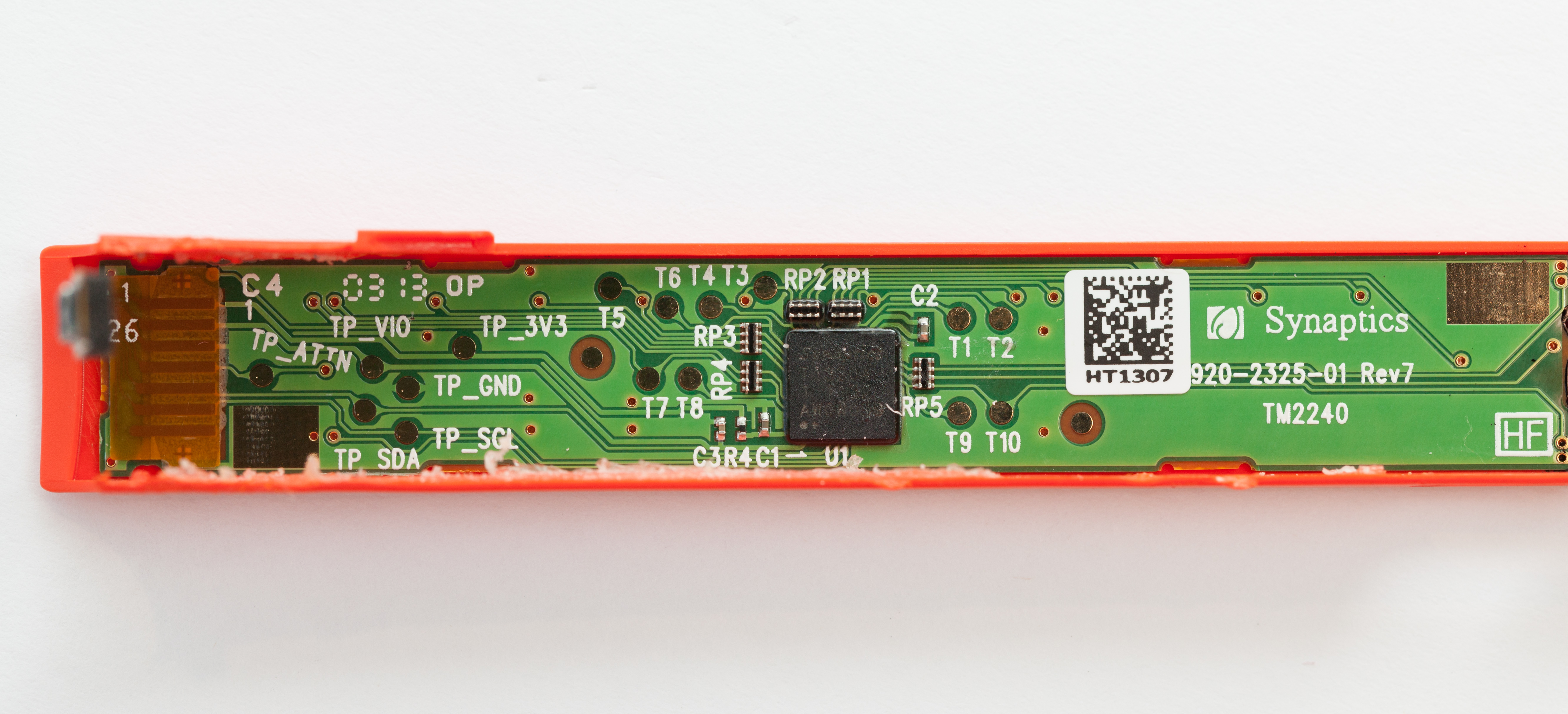
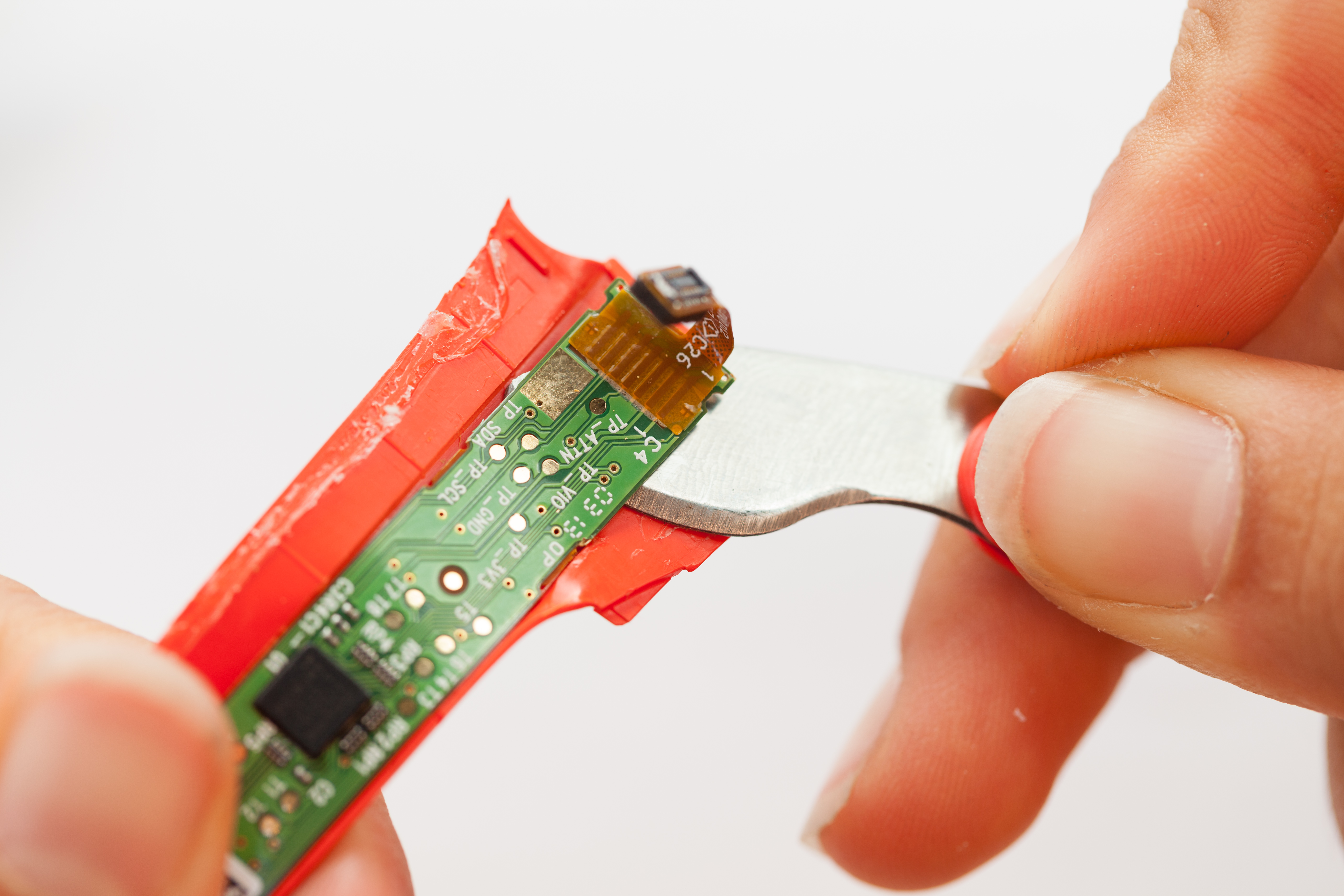
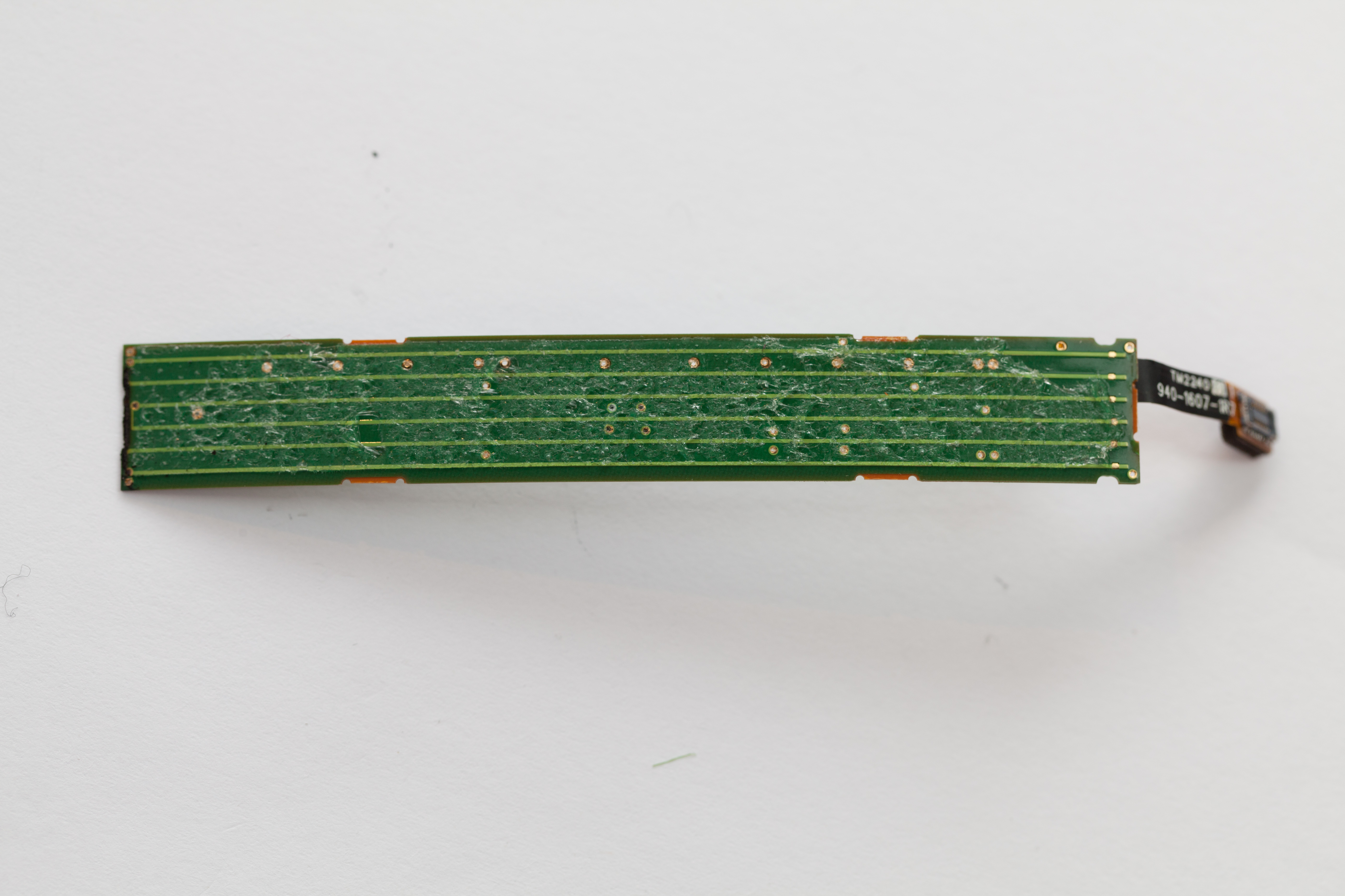
Side Touchpad
Removing the casing exposed a few parts, including the separate touchpad module on the right side of the unit. When a Glass users looks like they are pensively tapping their temple, they are interacting with this sensor. The touchpad is a full custom module made by Synaptics, and is driven by a Synaptics T1320A touchpad controller.
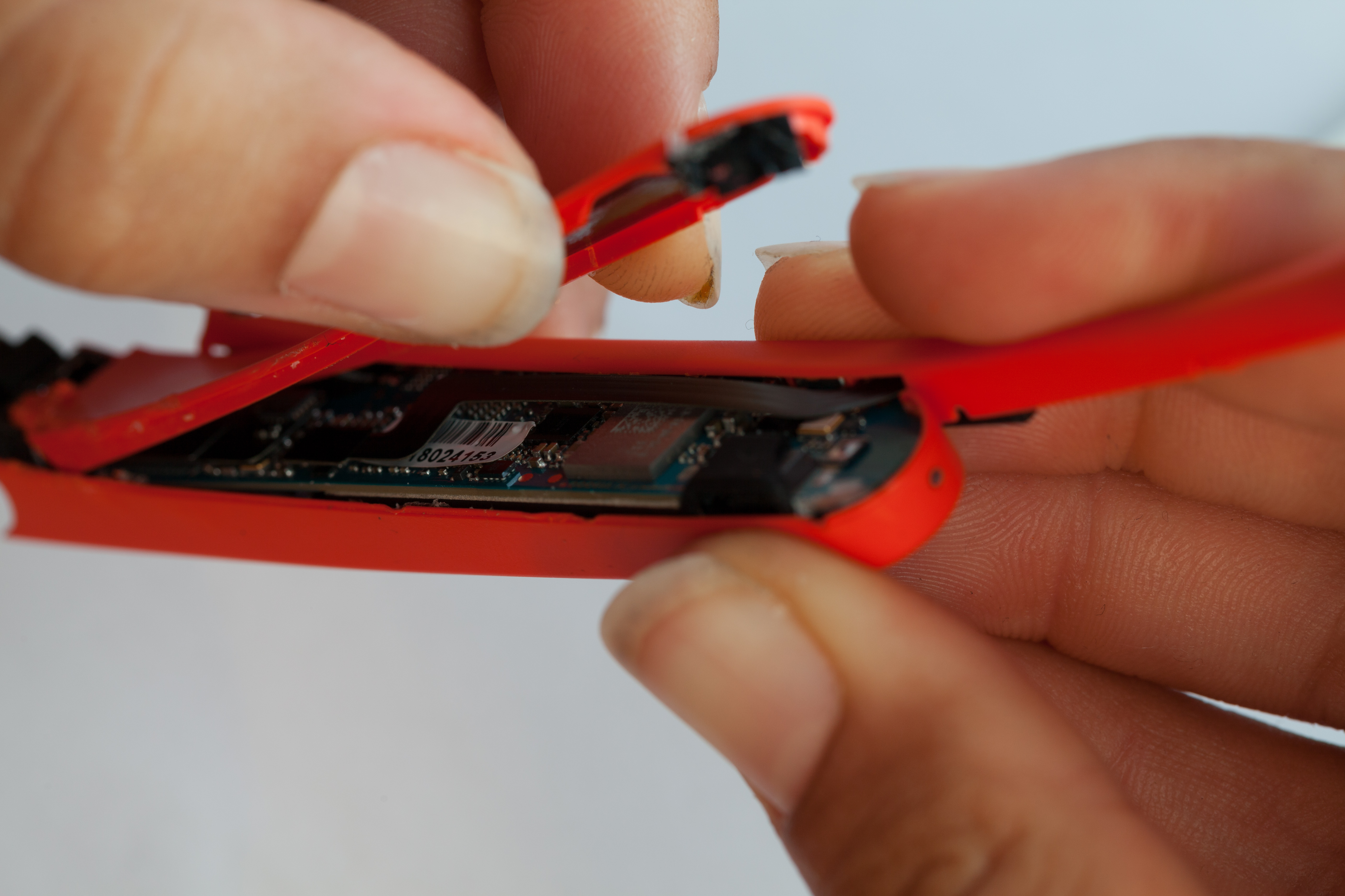
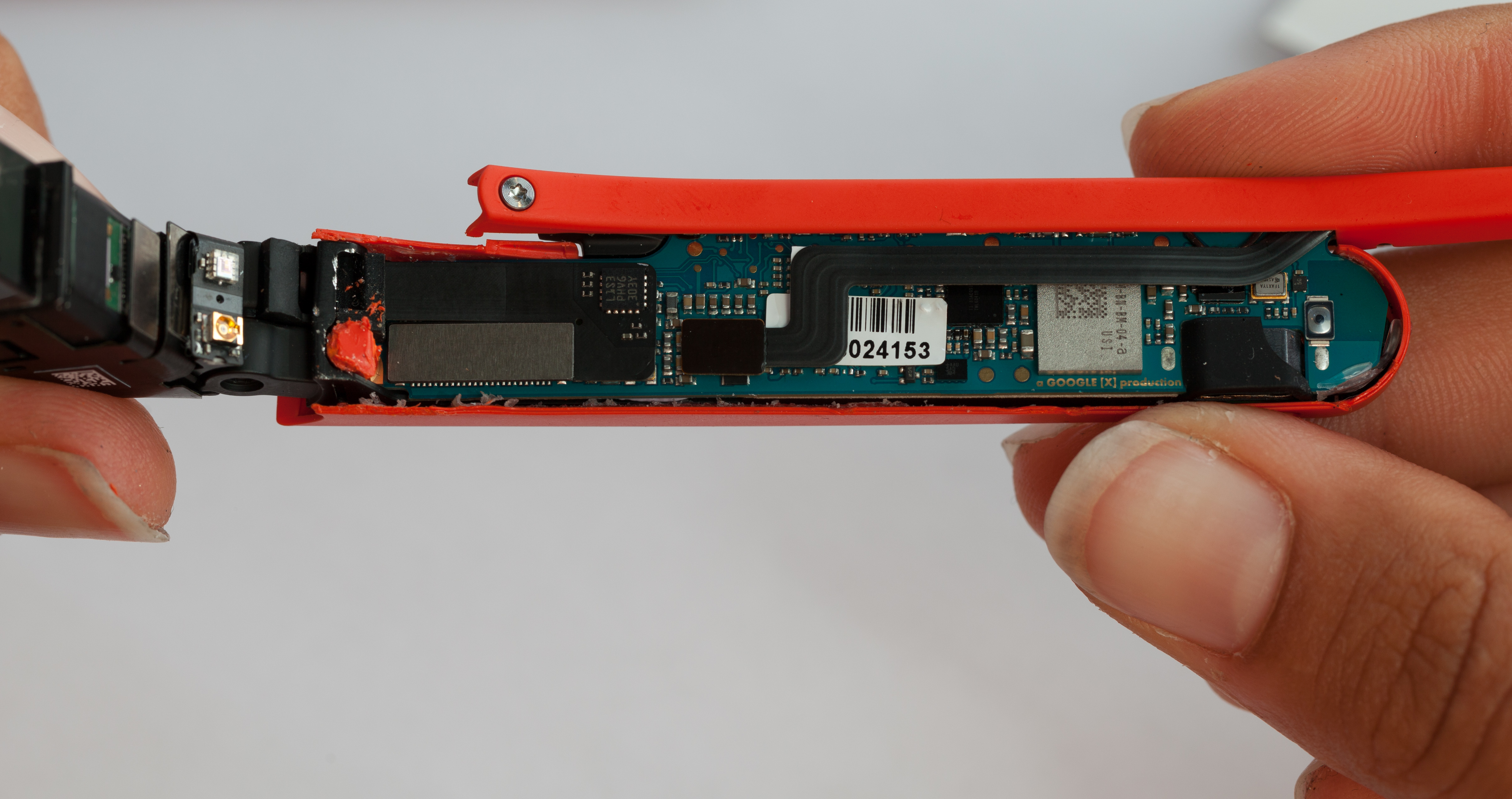
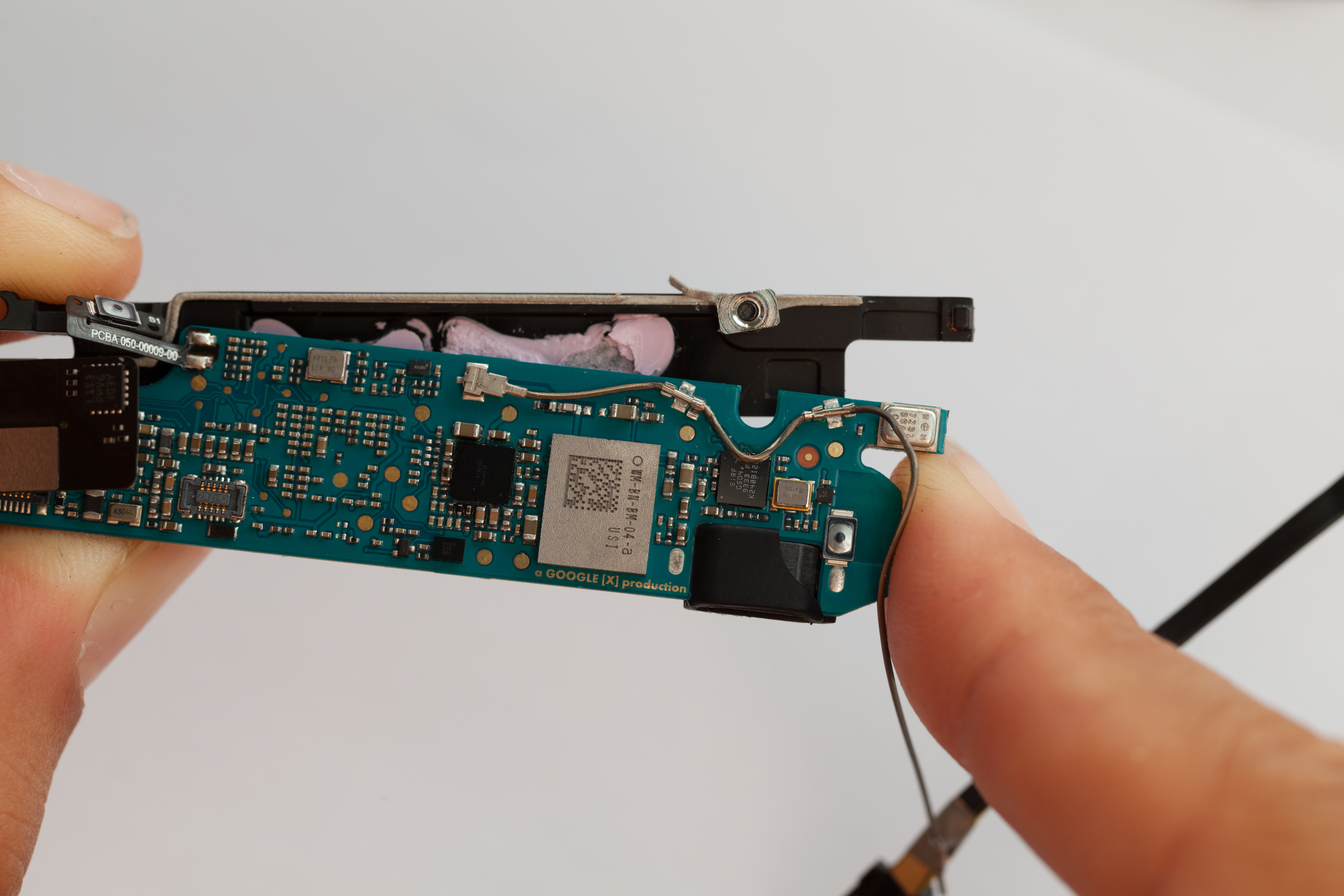
Main CPU Board
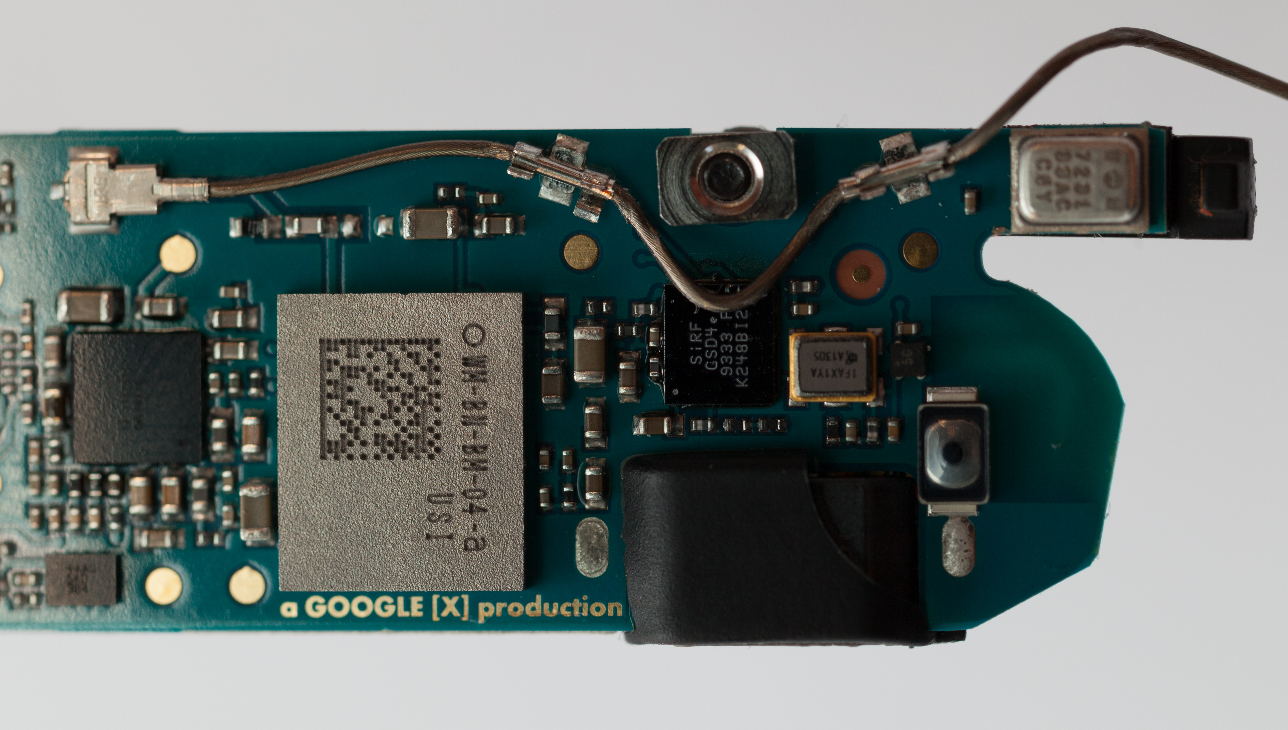
The main logic board was now exposed. The inwards-facing side holds an RF module, some small connectors and support ICs, and copper noting that this is "a GOOGLE [X] production".
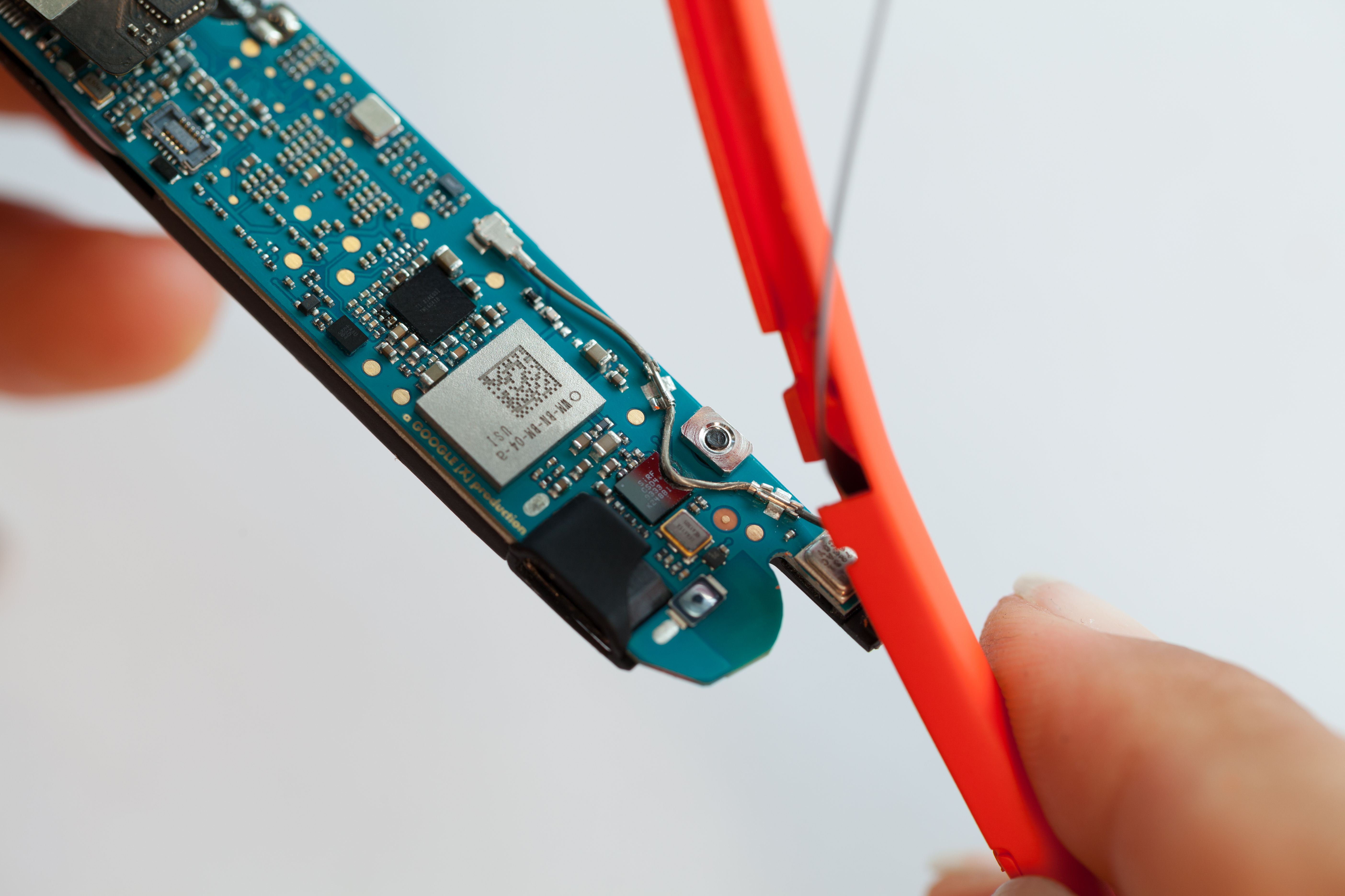
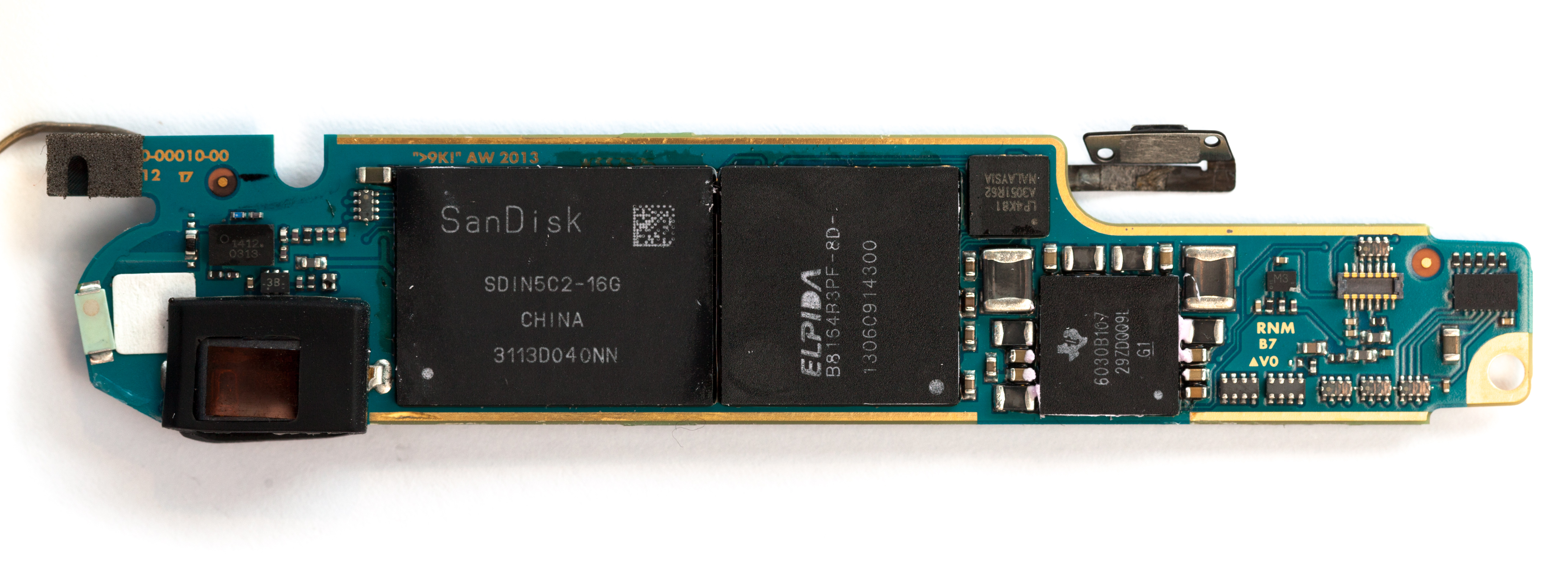
This board was stuck to a thermal pad with lots of paste. After removing it and cleaning off the pink thermal compound, we revealed the core chips powering Glass: a TI OMAP4430, 16GB of SanDisk flash, and an Elpida mobile DRAM chip. A flex PCB and an RF cable, anchored with some metal tabs and an MMCX (?) connector, trailed from this board to the behind-the-ear pod.
Some text in the copper on this board reads >9K! It's over 9000!
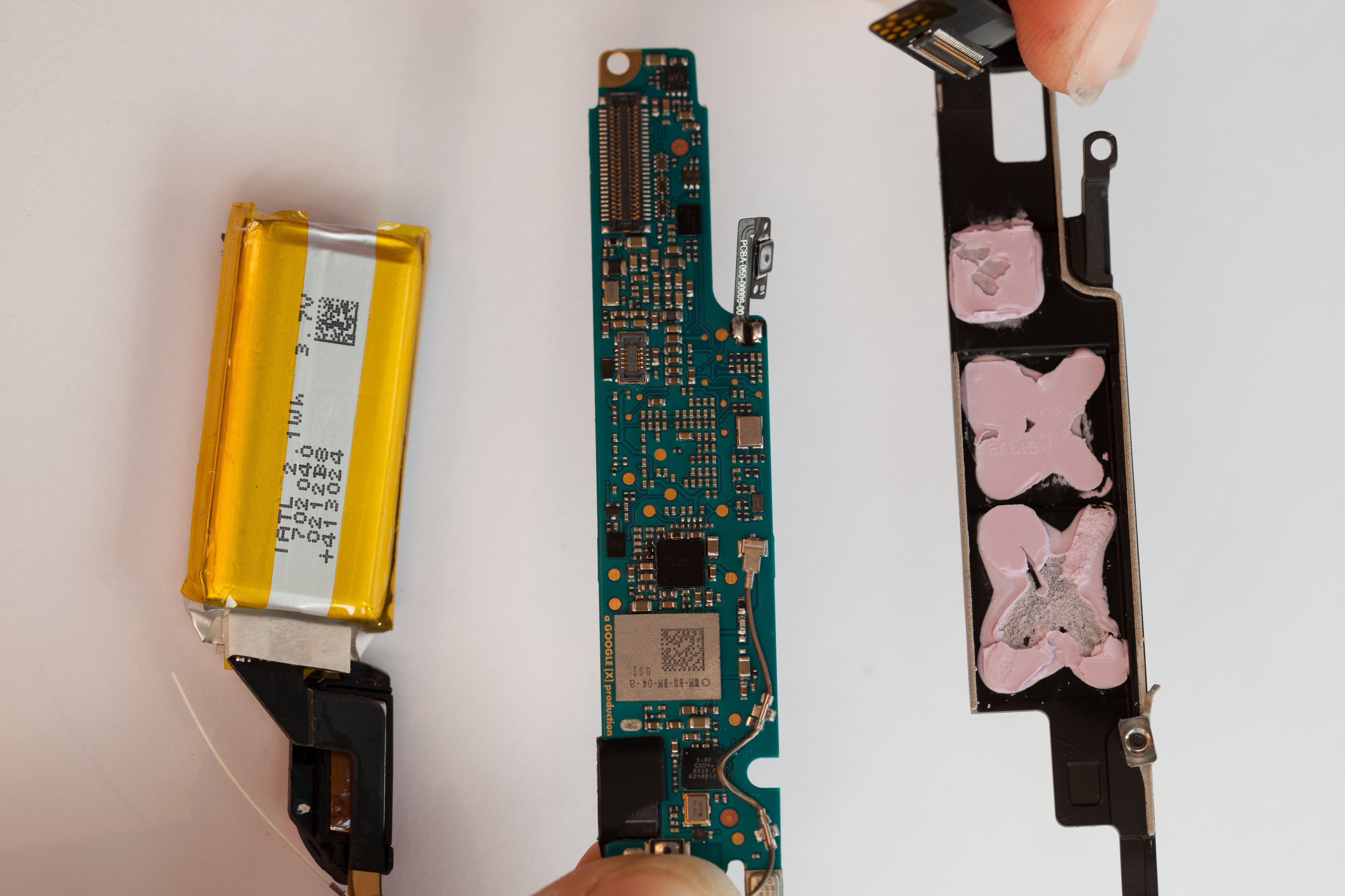
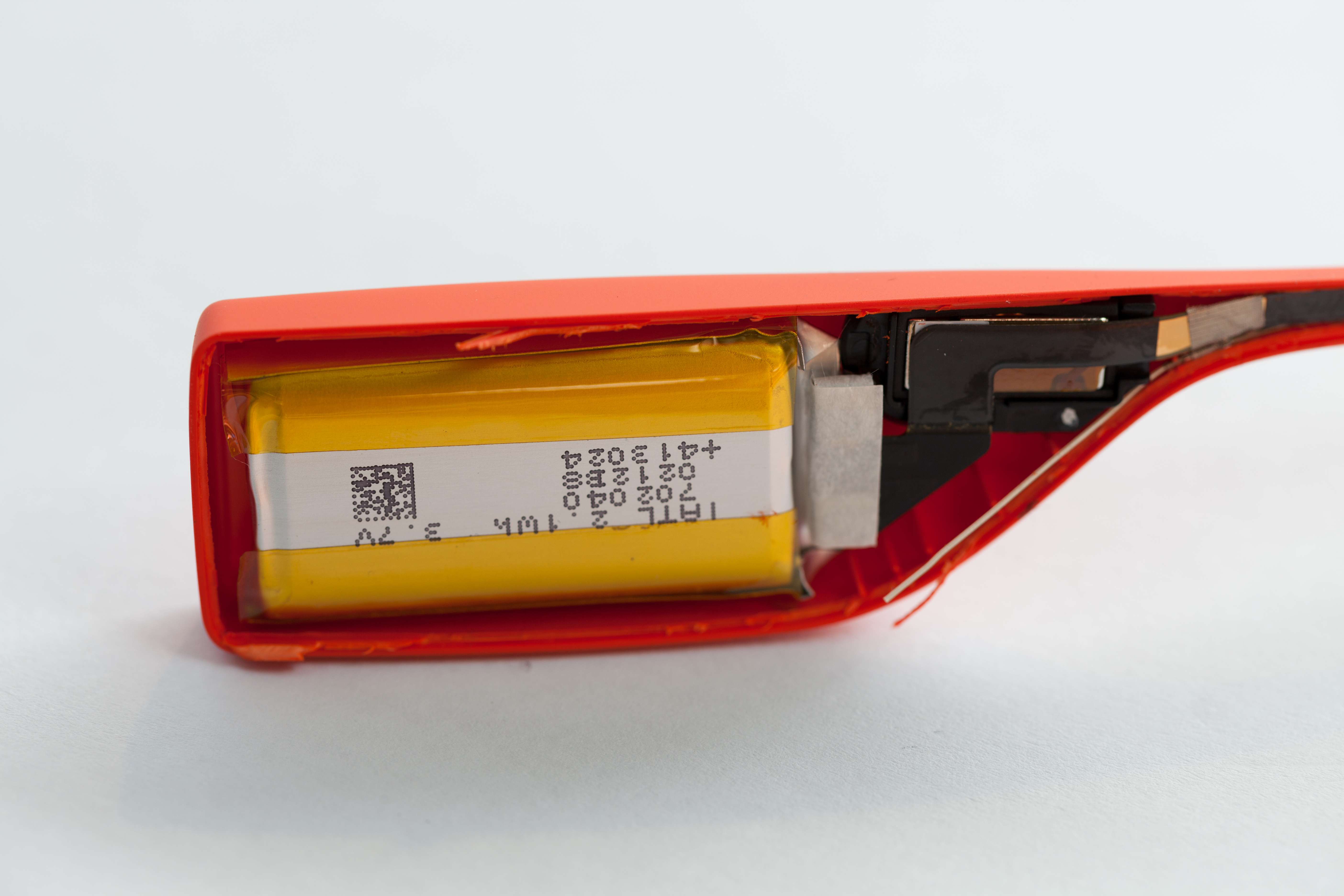
Behind-Ear Module
To keep the unit's weight distributed more evenly, Glass keeps its battery in a rounded bit behind the wearer's ear. We stripped this area open, again applying destructive force to tear the plastic.
The single-cell Lithium Polymer battery sits at the end of the flexprint PCB and is marked as having a capacity of 2.1 Wh (roughly 570 mAh). It is not user-replaceable, not even a little bit.

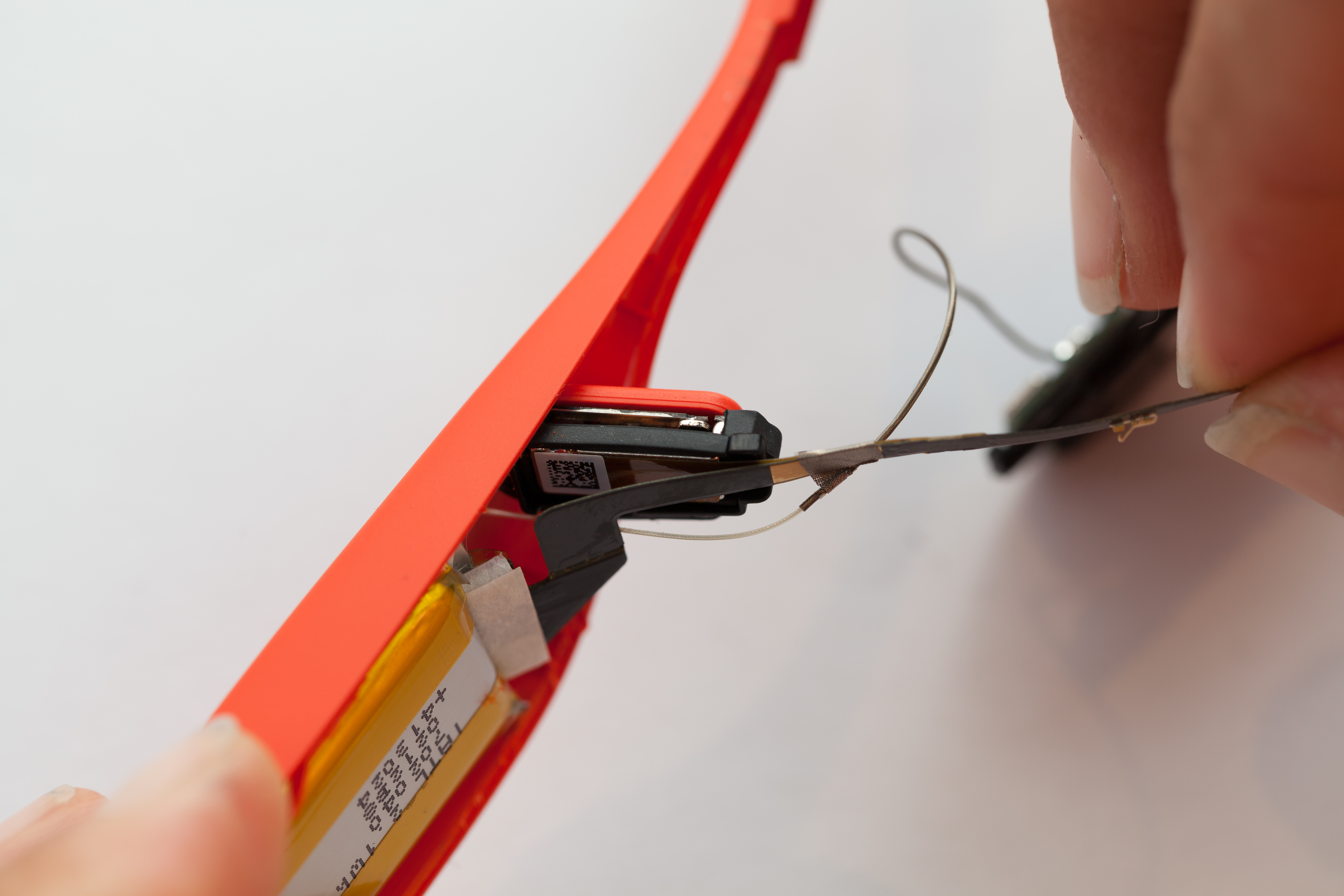
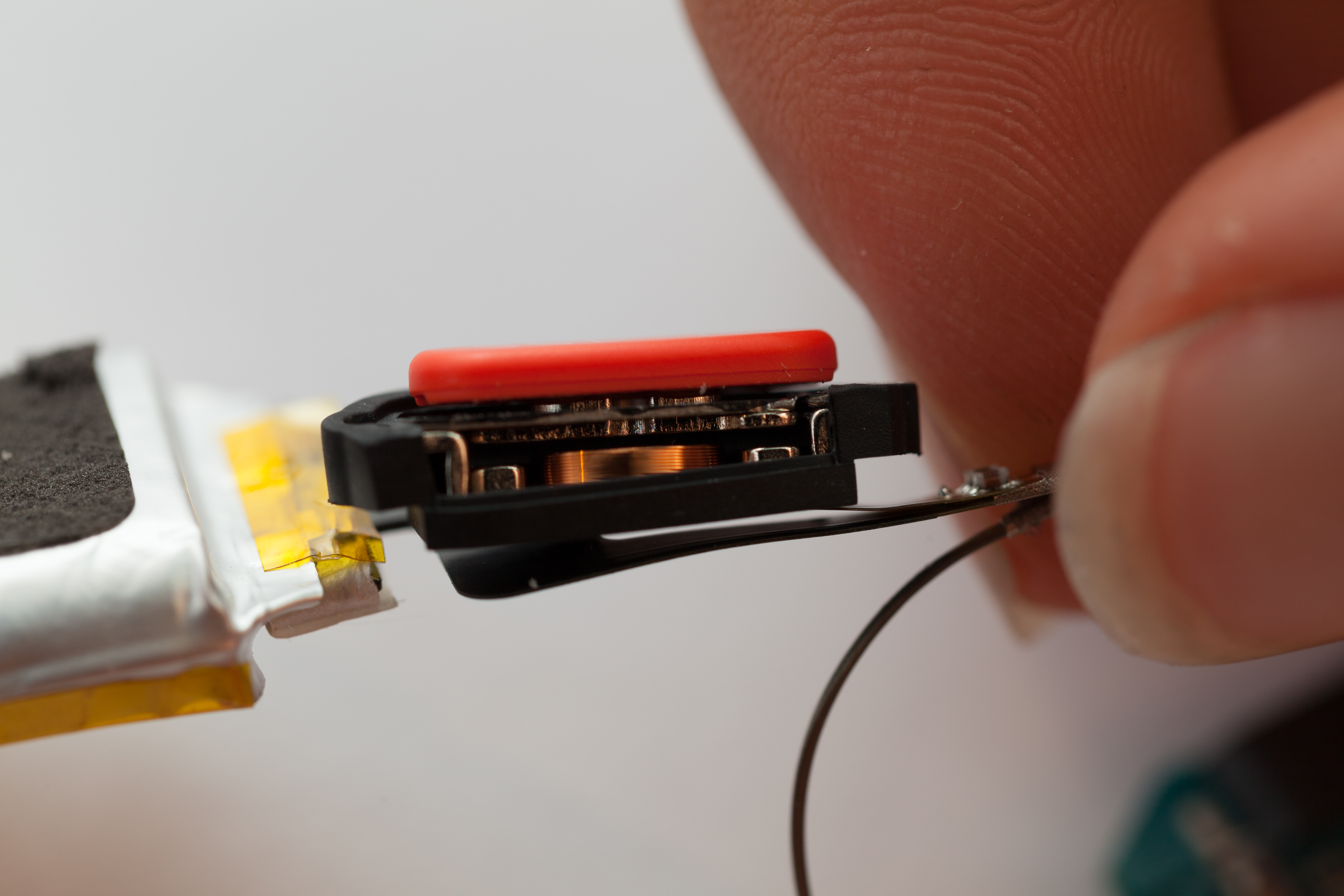
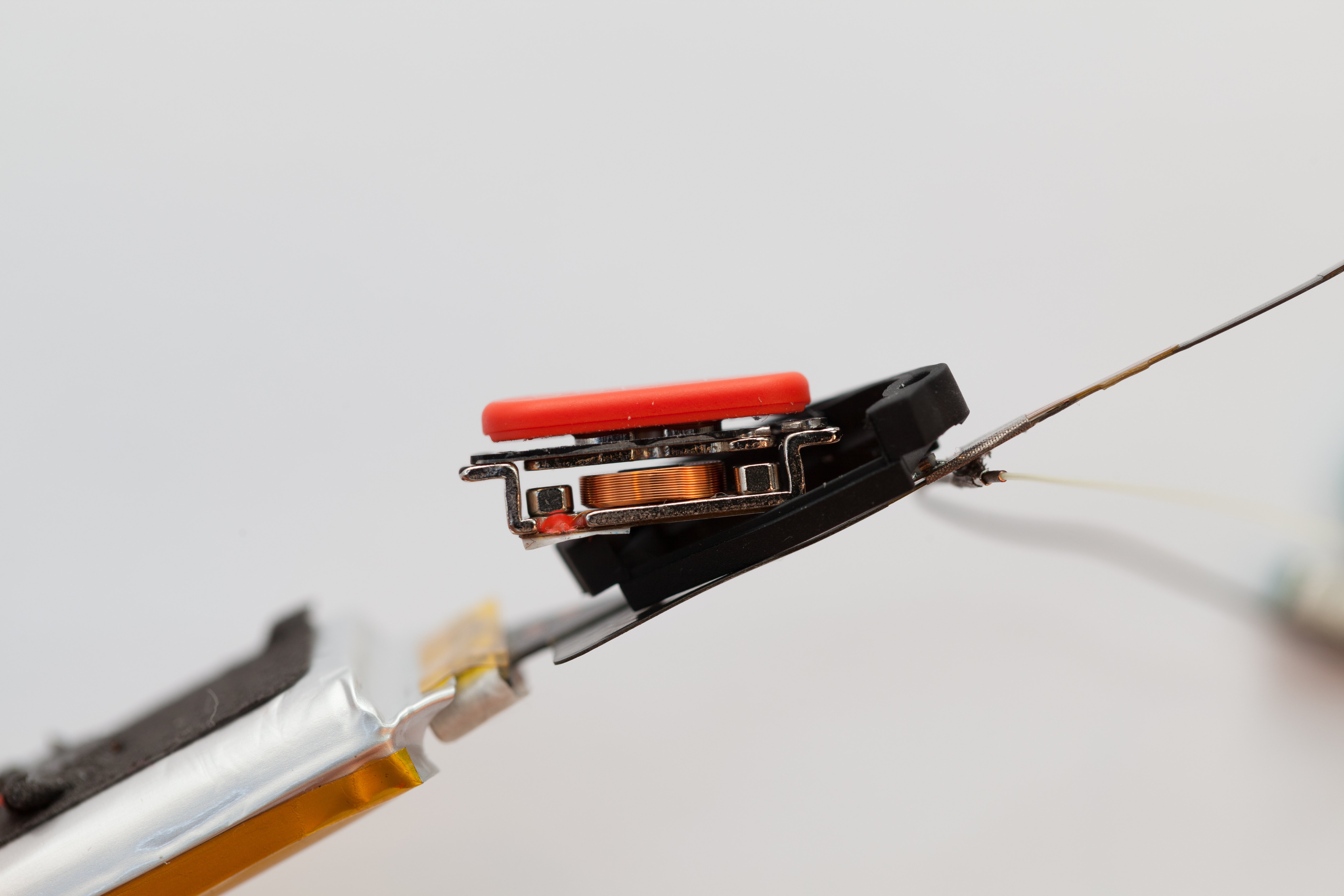
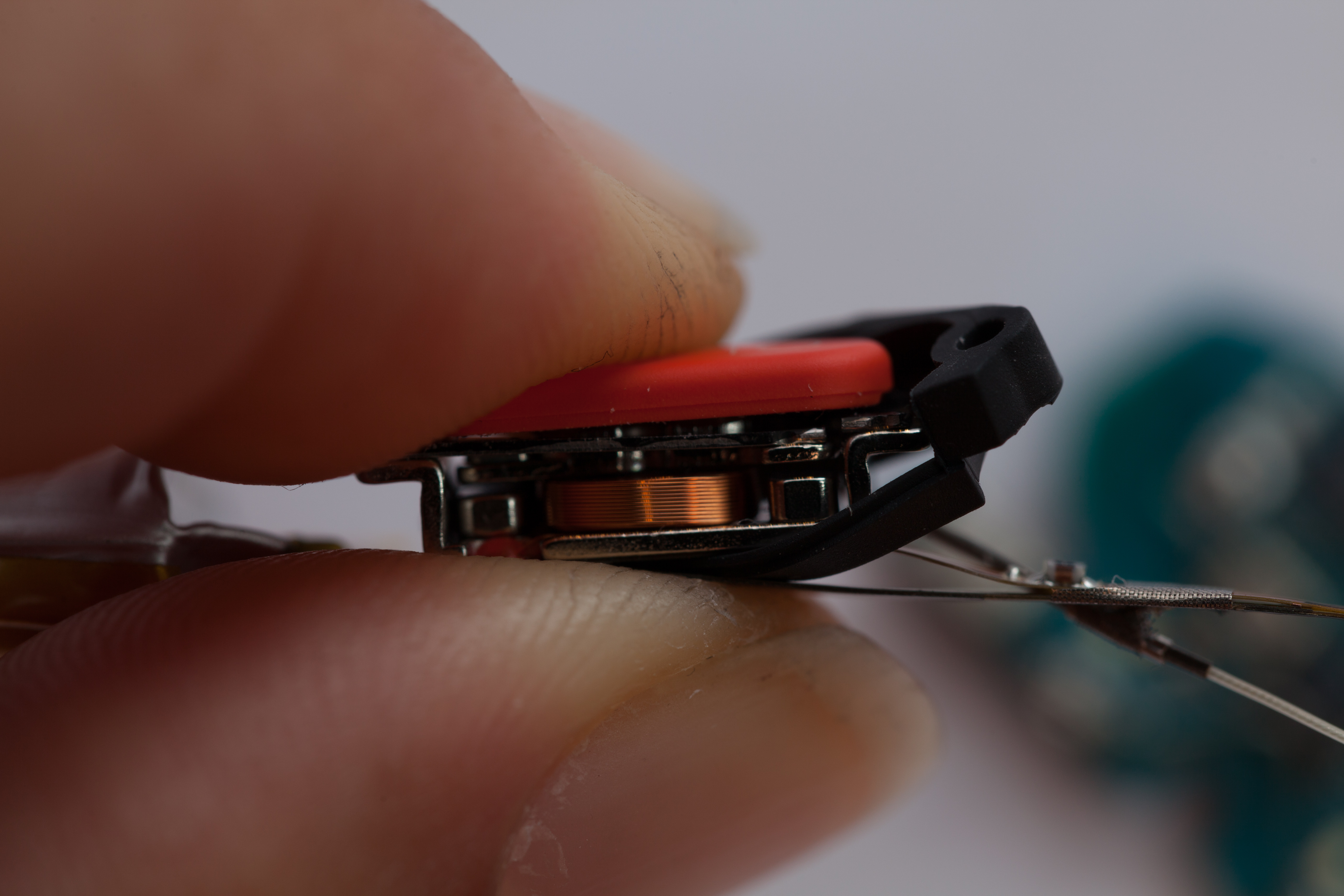
Speaker
Just forward of the battery pod is a bone conduction speaker, which seems to double as a tactile switch.
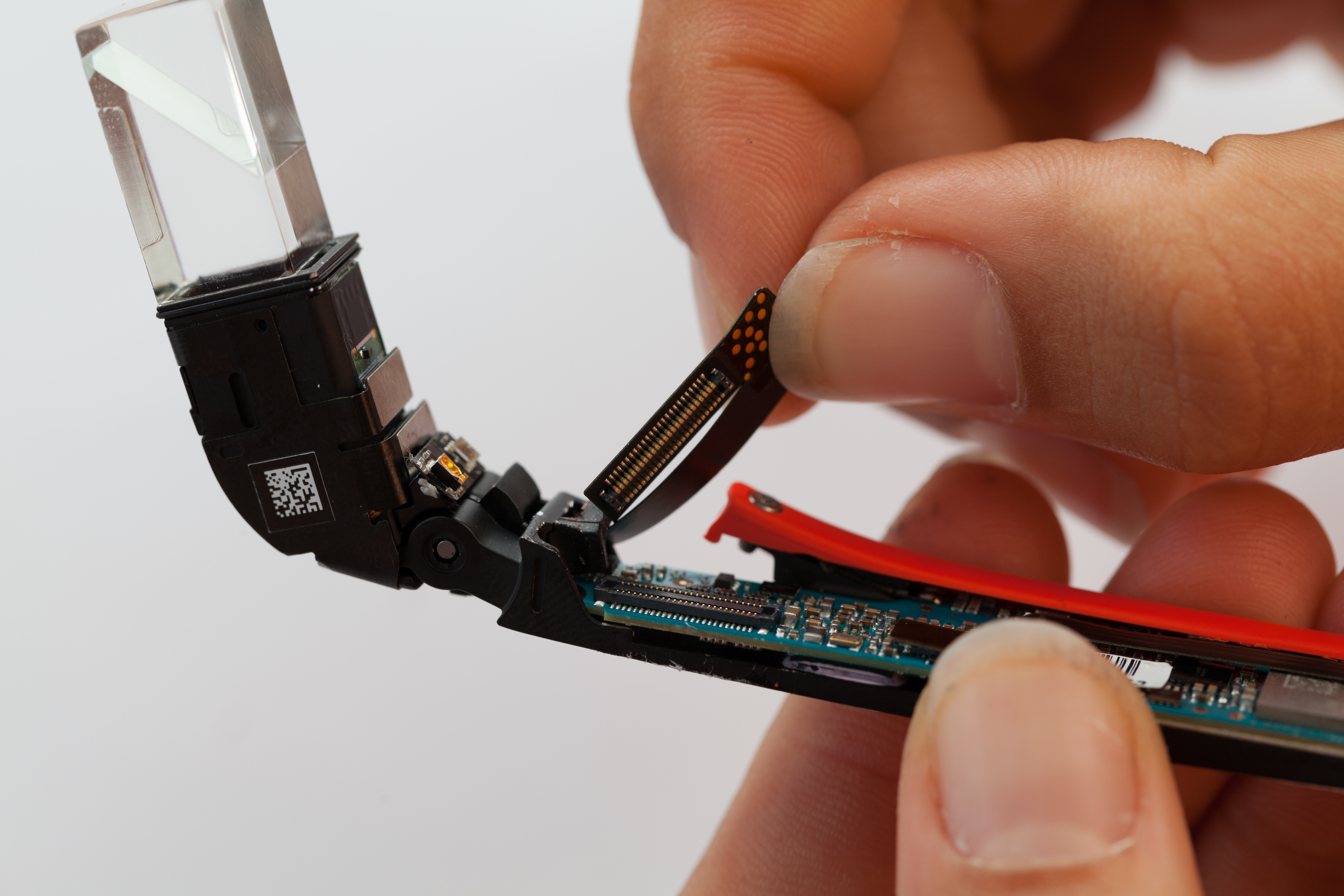
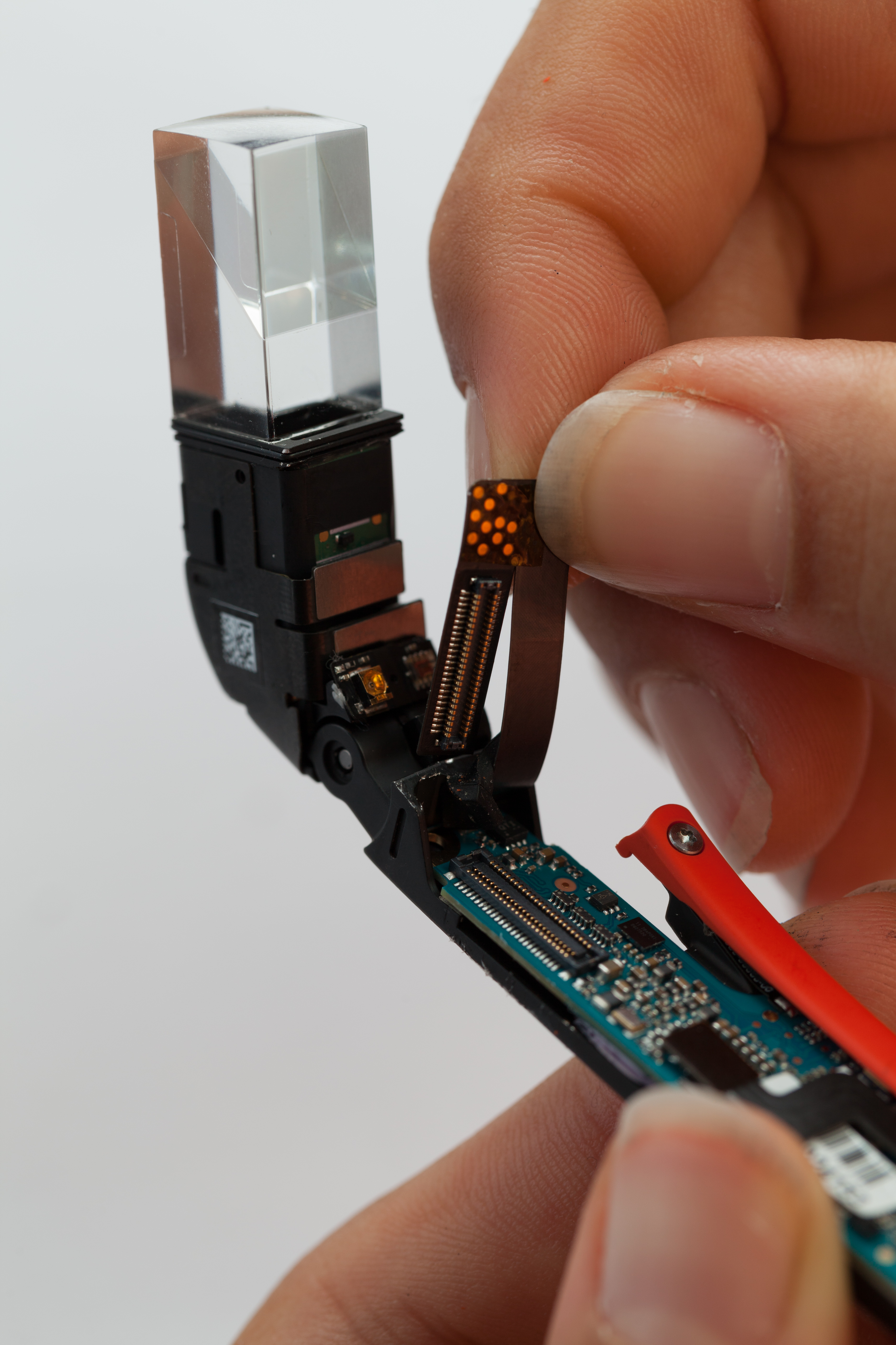
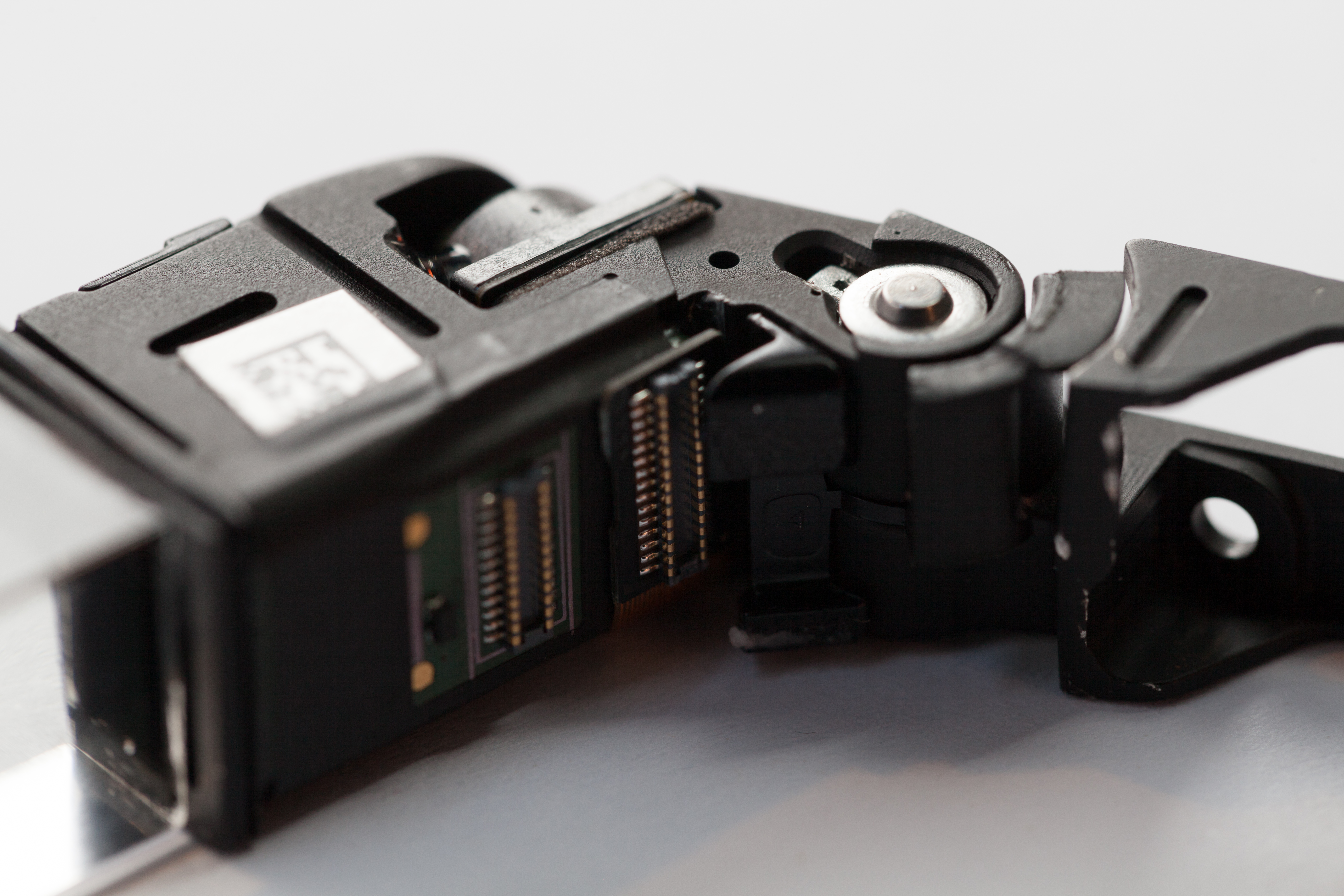
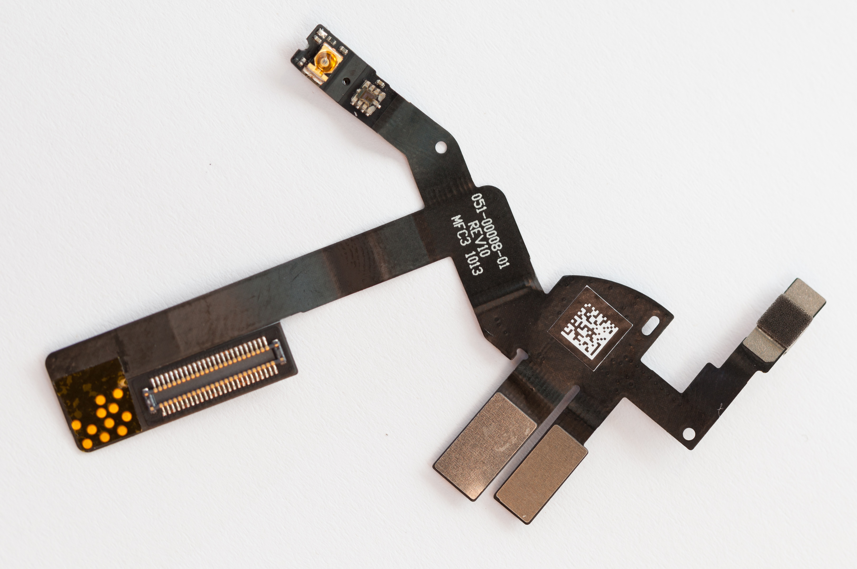
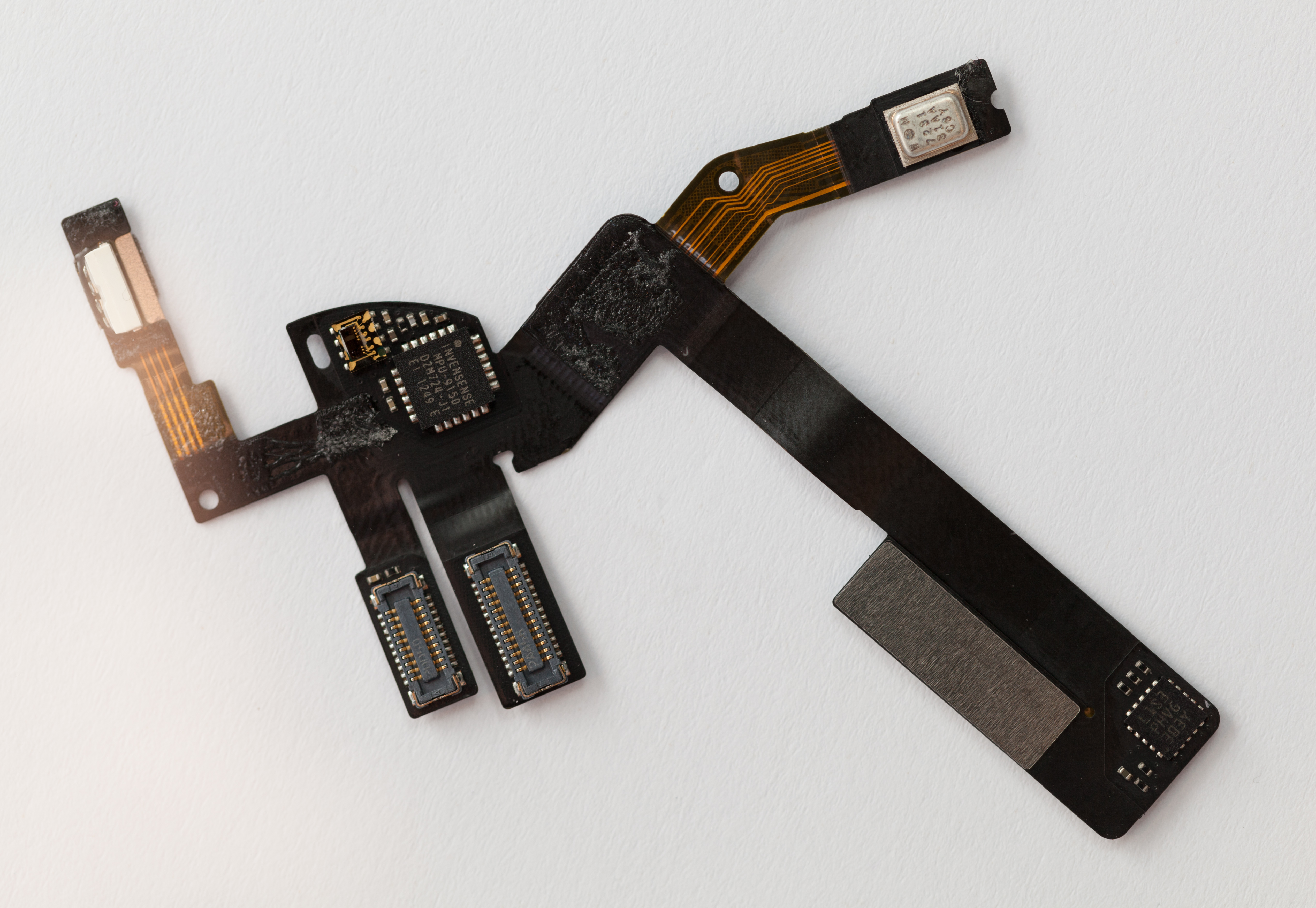
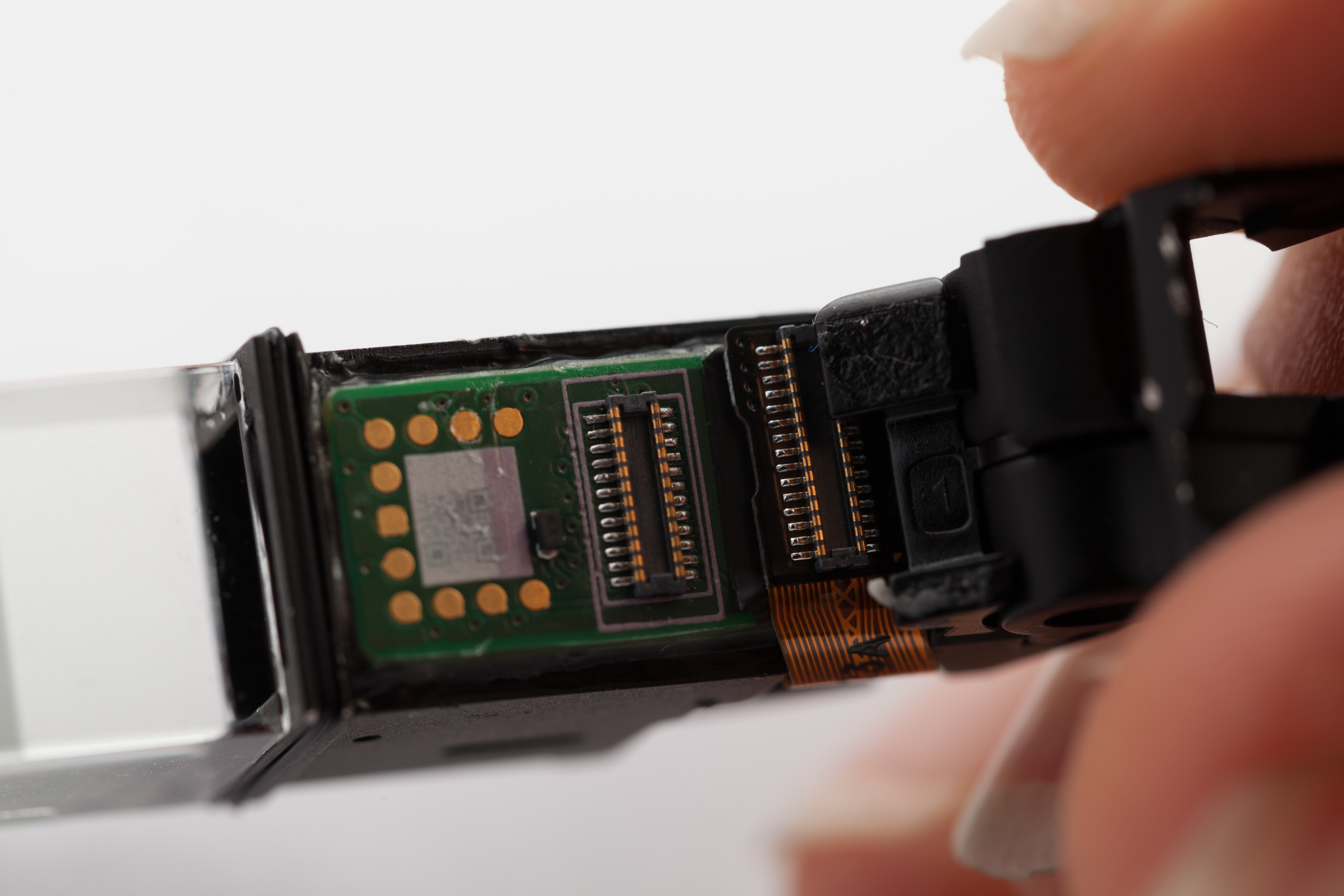
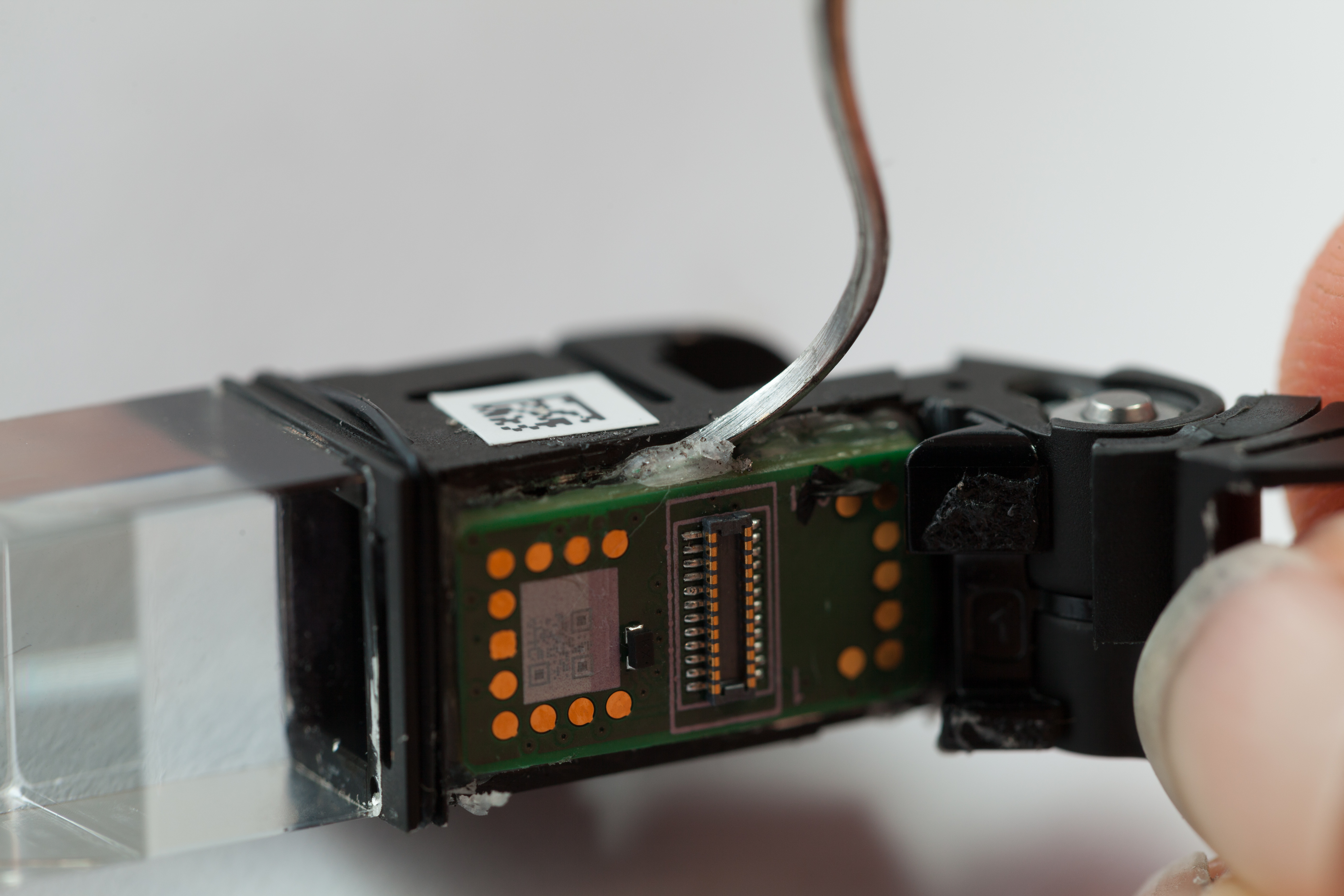
Display Assembly
Another flex PCB, this one much more intricate, connects the main logic board to an assembly containing the display, camera, and some other sensors. It wraps around and through the frame holding those components. We gently pulled it off its connectors and extricated it.
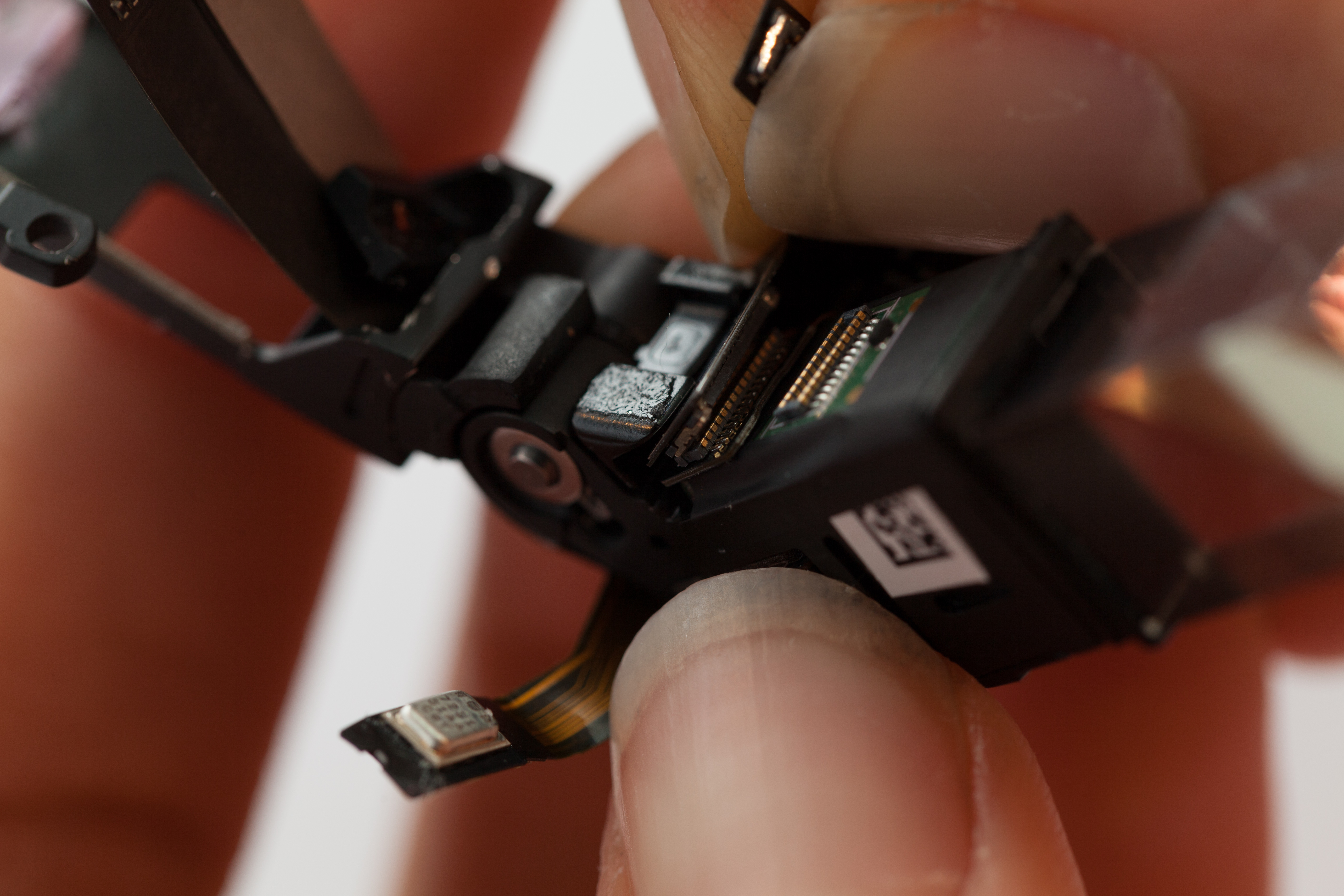
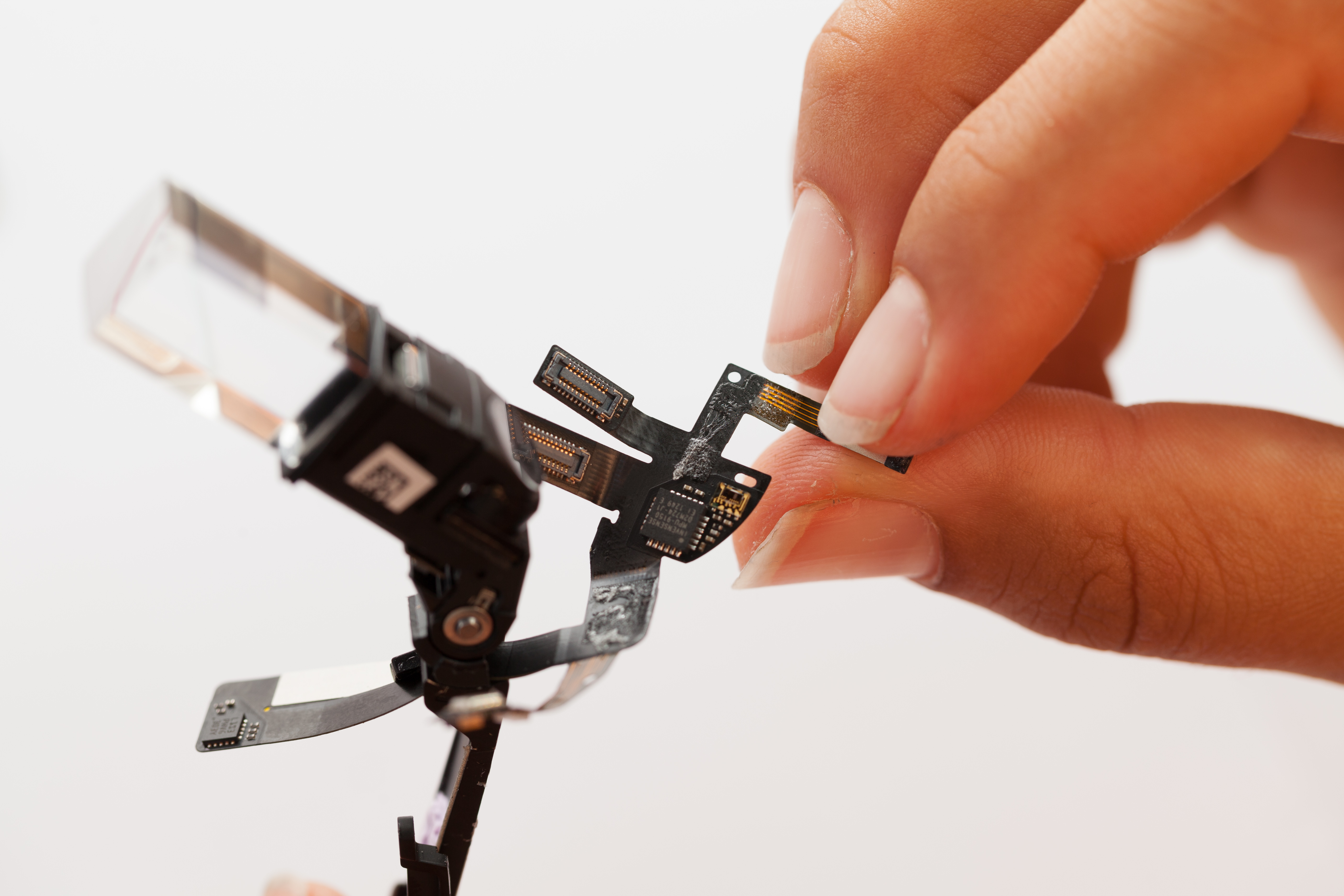
Among other things, the flexprint PCB holds Glass' inertial sensor, an InvenSense MPU-9150.
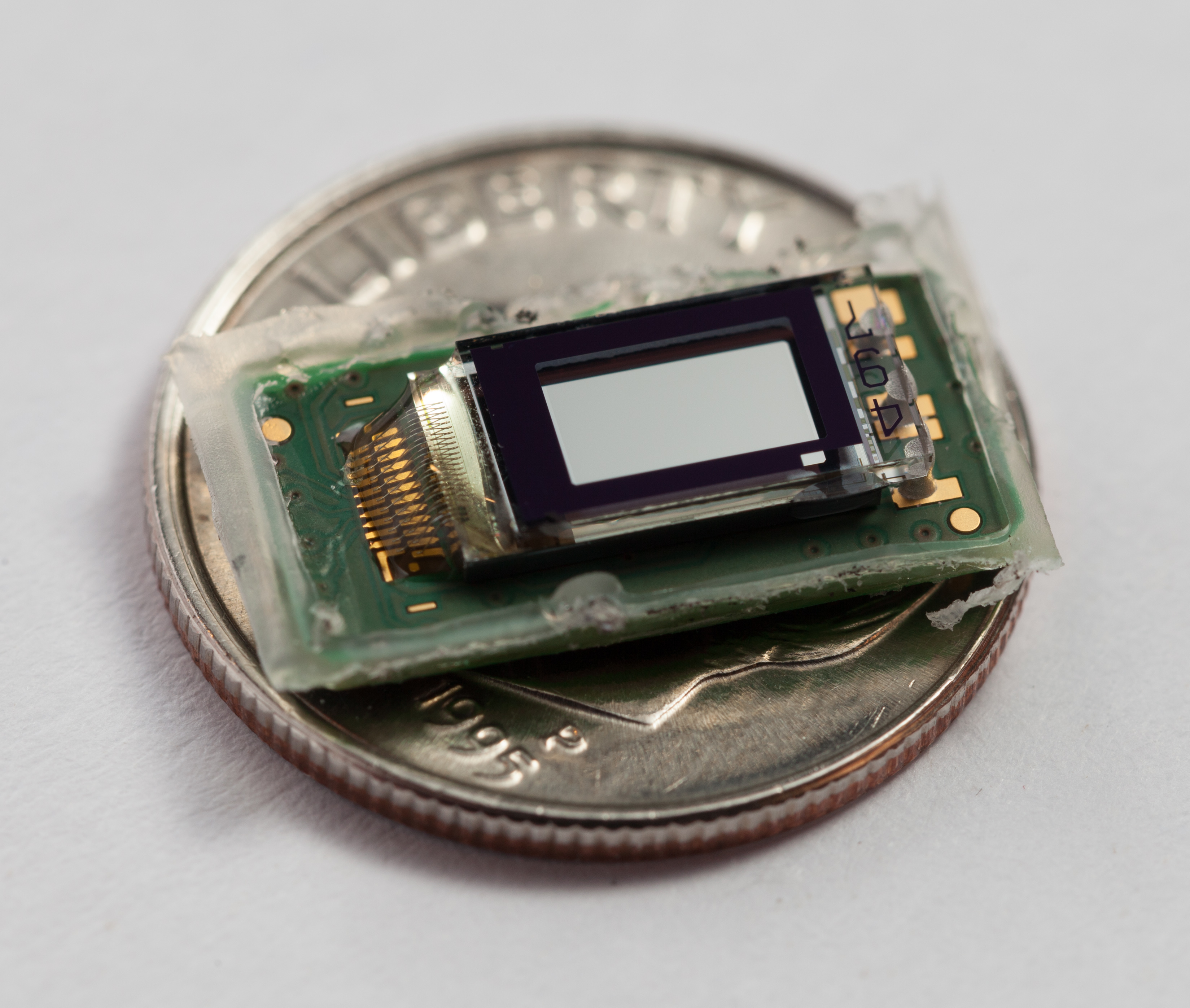
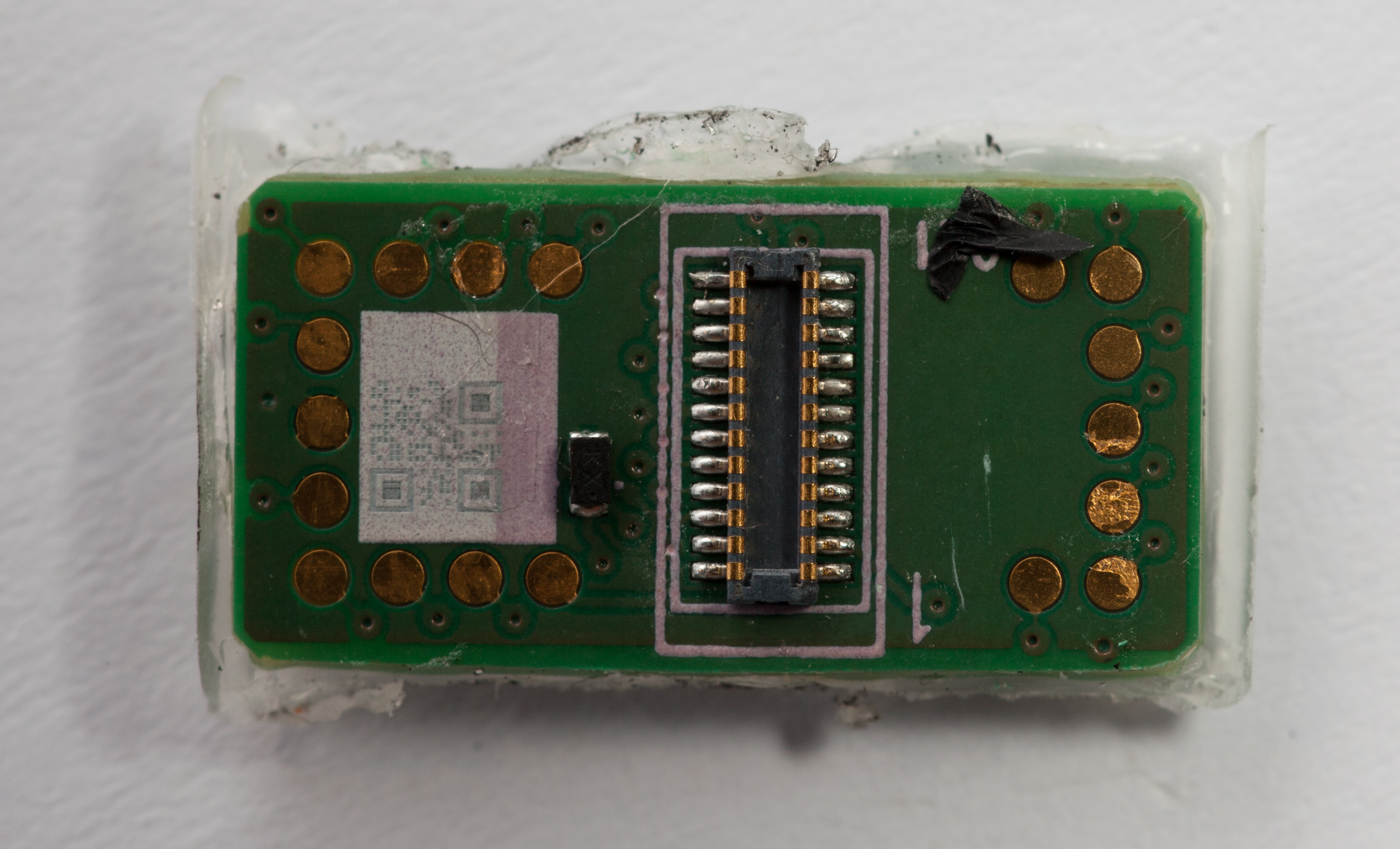
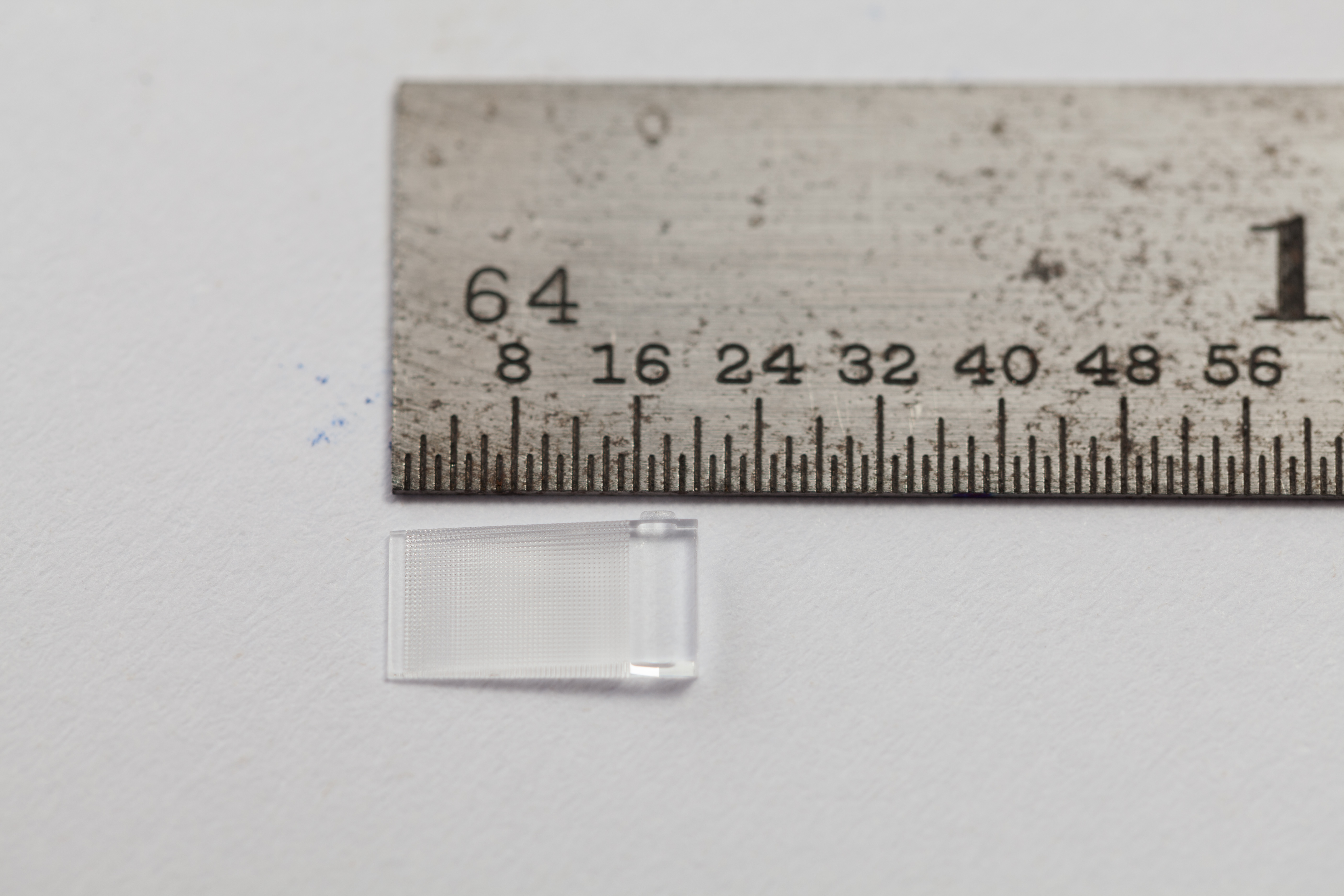
Display
The Glass display is very small. It is adhered to the inside of the internal frame with light glue around the edge of the display board. We scraped off the glue with a dental pick and removed the board.
For scale, it is shown pictured on top of a US dime. With a native resolution of 640x360, the pixels are roughly 1/8th the physical width of those on the iPhone 5's retina display.
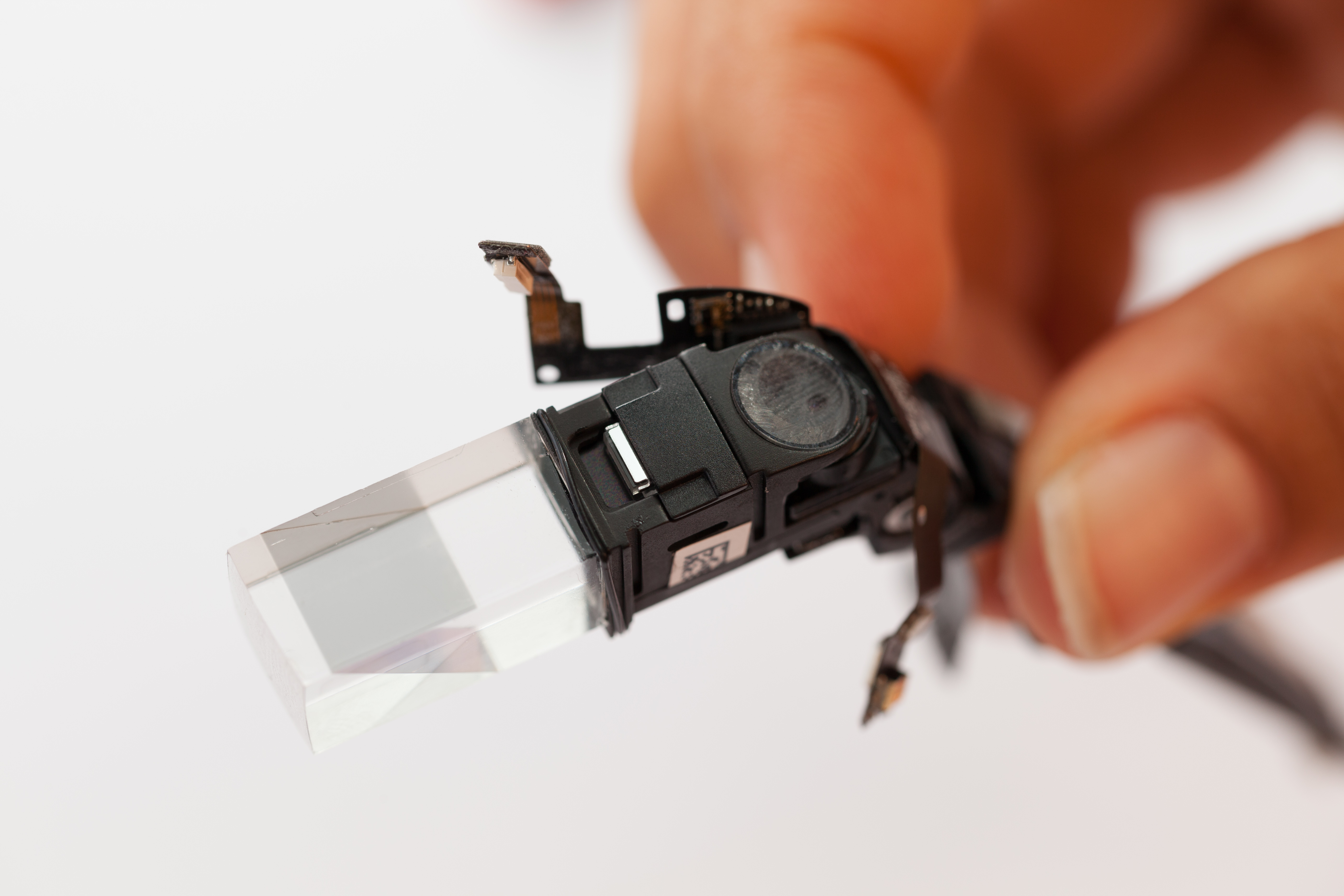
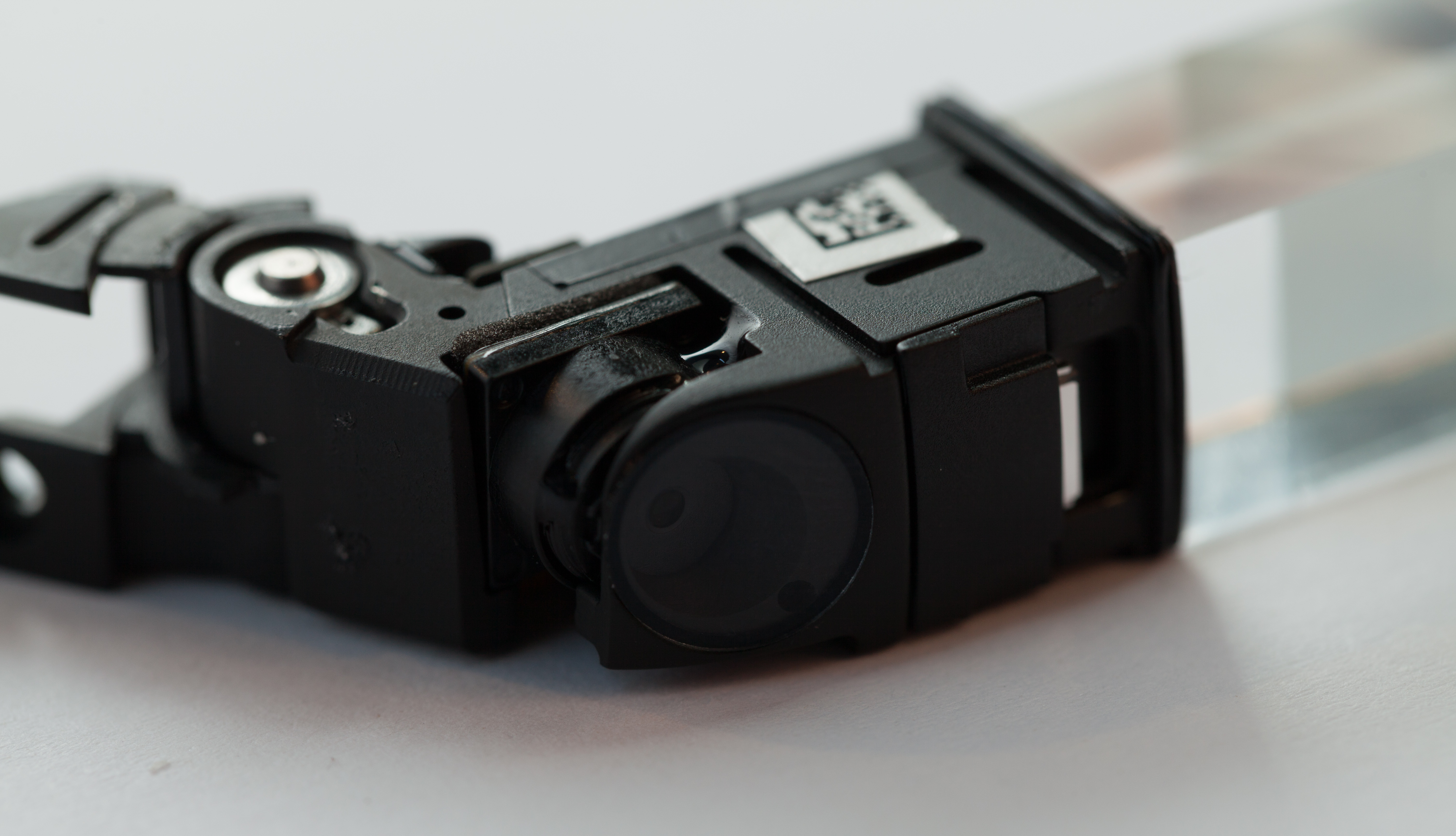
Optics
Glass uses a folded light pathway consisting of only a small handful of optical elements. Collectively they make the display's image appear to float a few feet from your face, in the top right corner of your vision. Steve Mannexpands upon these optical strategies in much more detail and describes some additional challenges.
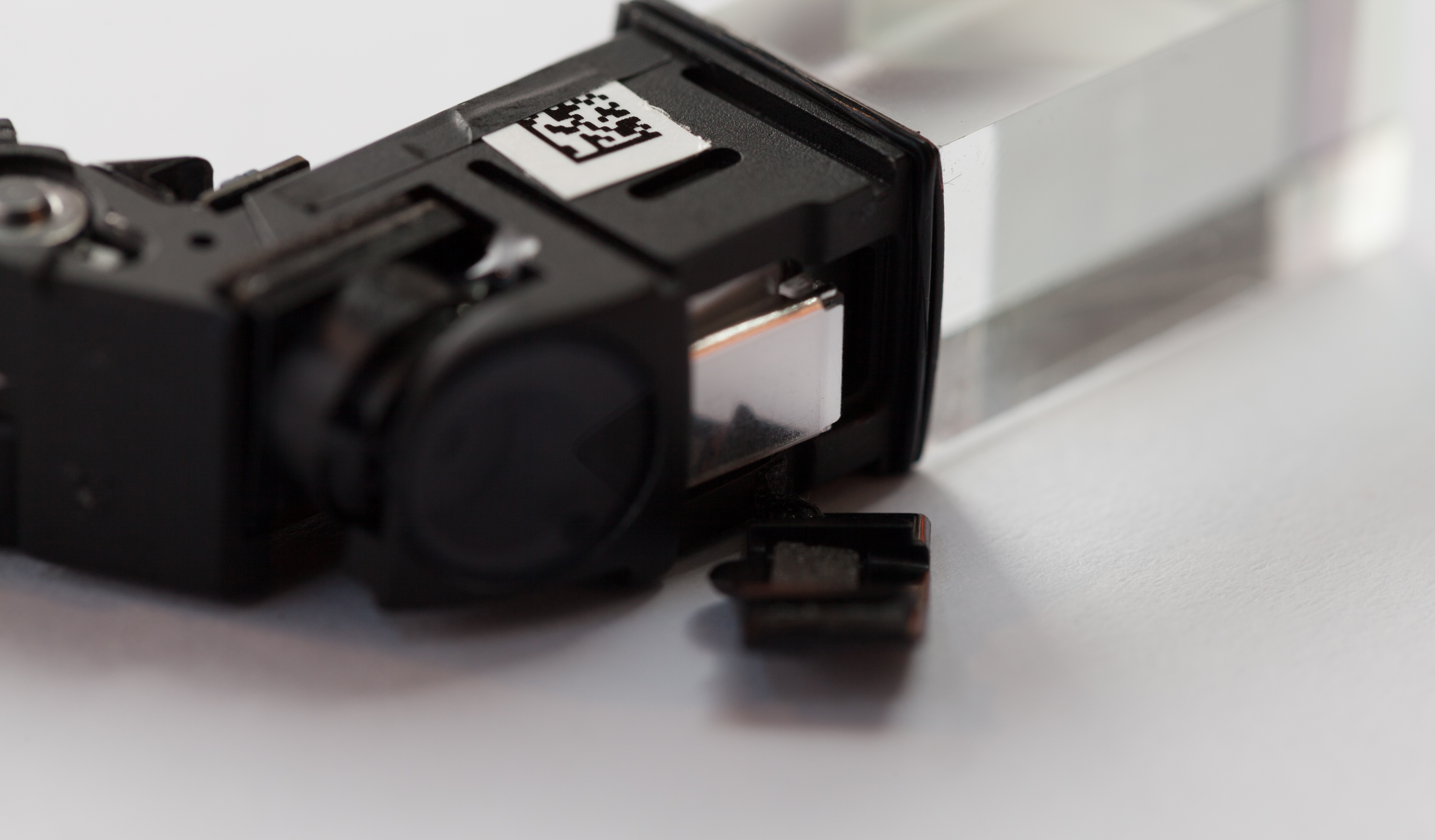
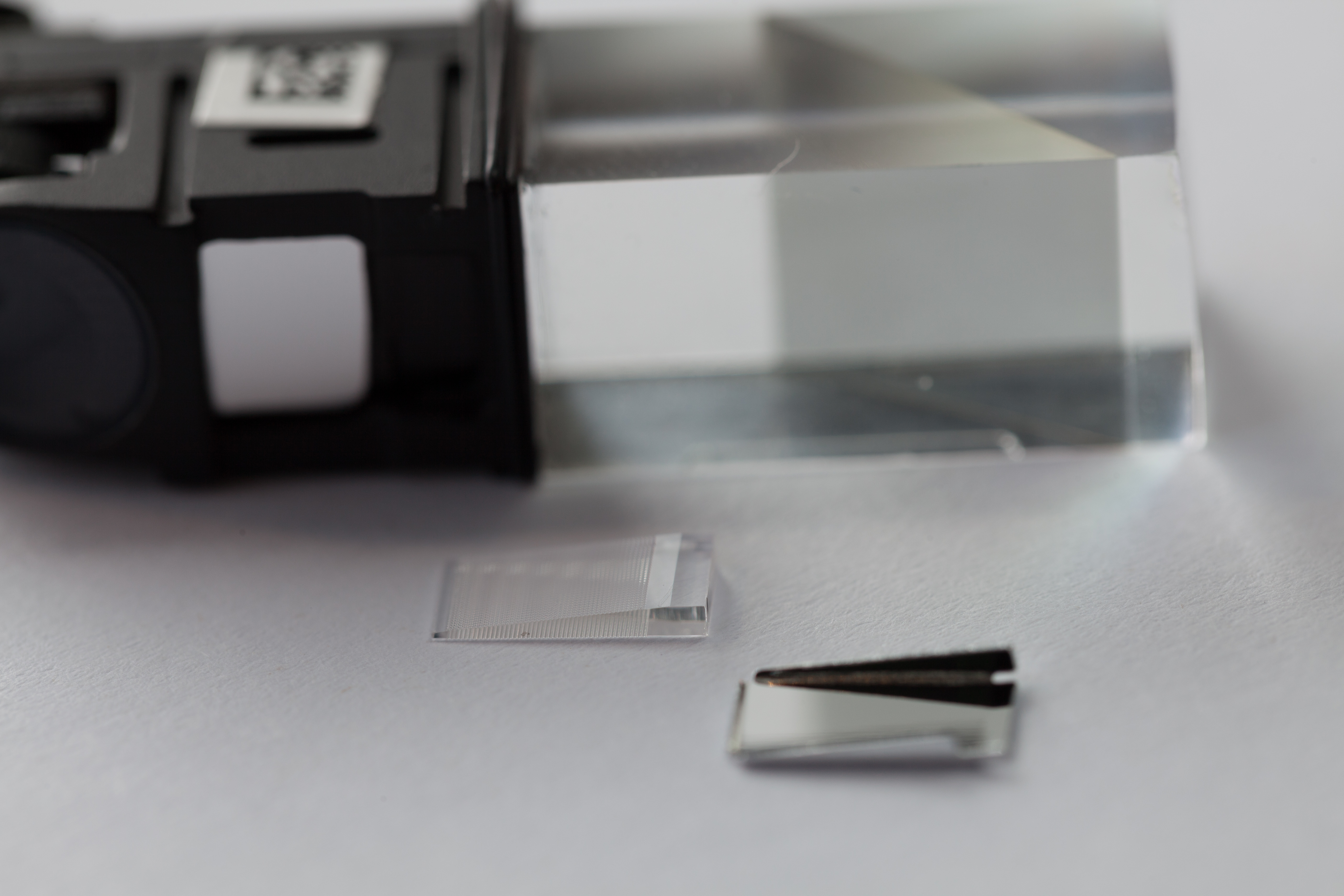
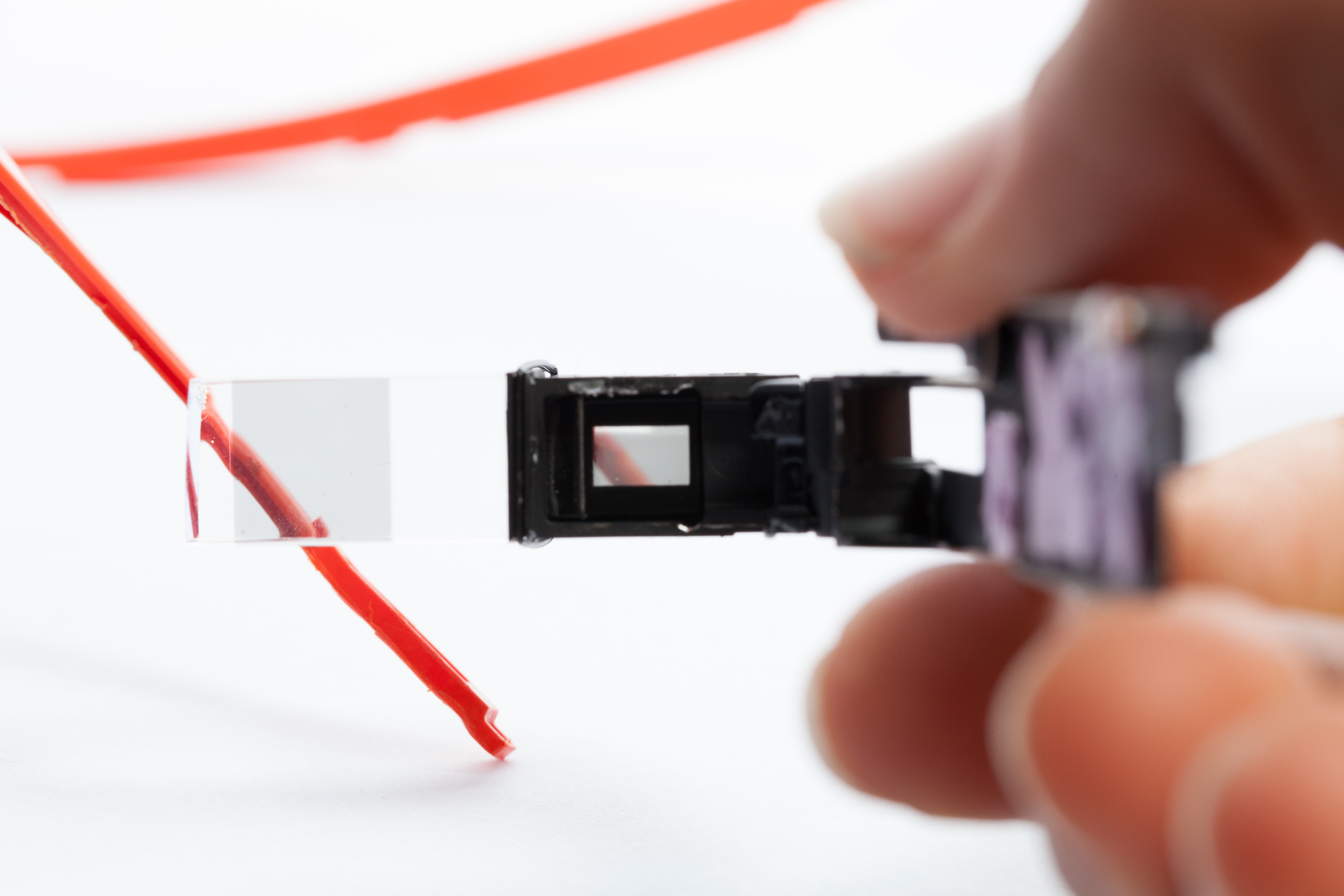
In the final photo, you can see this optical pathway at work when the display is removed.
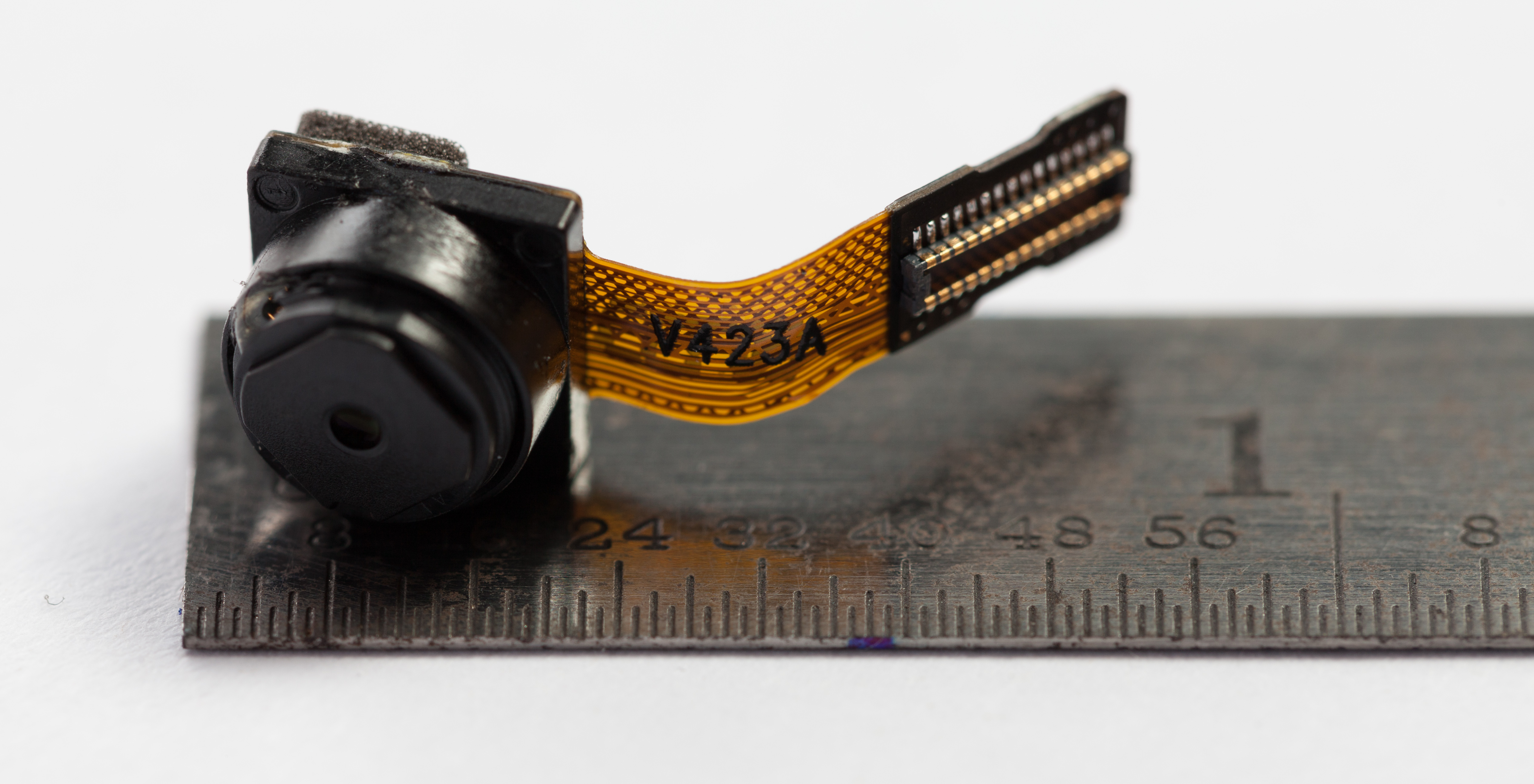
Camera
The Glass camera seems to be of typical smartphone-level size and format. It is not coaxially aligned with the wearer's eye. The camera and display appear to talk to the CPU independently, with no direct connection between each other.
We took some sample photos through Glass.


Special thanks to Sparkfun for sponsoring this teardown and supporting electronics education everywhere.


 留言列表
留言列表